Liquid level detection device and liquid level detection method

A liquid level detection and detection device technology, which is applied in the field of metal billet production, can solve the problems of interference of measurement results, influence of measurement results, irregular size changes, etc., and achieve correct control of liquid level height, safe working environment, and stable measurement results Effect

Pending Publication Date: 2019-01-18
XIAN METALWK HYDRAUMATIC MACHINERY
View PDF12 Cites 12 Cited by
  • Summary
  • Abstract
  • Description
  • Claims
  • Application Information

AI Technical Summary

Problems solved by technology

[0013] (2) In casting production, in order to remove harmful components such as S and P and prevent metal oxidation, it is necessary to continuously add mold slag to the crystallizer. Maintaining the correct thickness and orderly distribution of mold slag can effectively improve the quality of casting blanks. Due to the weight of mold slag The impact of changes, and for high-temperature metal melts, there are many difficulties in measuring its flow in a long-term, stable and accurate manner, so the liquid level height value is obtained by calculation method, which has serious disadvantages in practical application. The error is large; especially important, this method based on weight calculation is used to calculate the liquid level of metal solution in a static container
This kind of friction is unstable, and its size changes irregularly, which will inevitably lead to the failure of the weight calculation method
[0014] (3) In the continuous casting production process, as the metal liquid level drops in the later stage of casting, due to the action of the earth's deflection force (Coriolis force), a confluence vortex will be generated on the metal liquid surface, and the confluence vortex is for the eddy current type and electromagnetic type The measurement results of the induction method cause serious interference, and the high-speed confluence vortex has a great impact on the surrounding electromagnetic field, which affects the measurement results, and in severe cases, it may cause accidents such as overflow or leakage of the metal liquid;
[0015] (4) Use the radiation source type induction method to measure the liquid level height, use the isotope radiation source, and use the scintillation crystal receiving device to receive the radiation that changes with the height of the metal liquid level, so as to detect the liquid level height, but the fatal disadvantage of this method is that there is radiation , endanger the health of workers, and the working environment is bad, so it is not suitable for use;
[0016] (5) The infrared induction method is suitable for the open pouring method without mold powder, and is easily affected by water vapor, smoke, etc., and this method is rarely used;
[0017] (6) The laser method is used to measure the liquid level height. Since lubricating oil is added to the mold as a lubricant during the continuous casting casting process, the lubricating oil is immersed in the metal liquid surface from the side of the mold and burns on the metal liquid surface, resulting in Flame and smoke, the brightness of the flame is close to the brightness of the metal liquid level, making it difficult to distinguish the intersection line between the metal liquid level and the inner wall of the crystallizer; the smoke is black and covers part or all of the image, which will lead to a false liquid level image, making the metal The measurement results of the liquid level fluctuate greatly, causing the computer to fail to provide the correct control amount, which affects the casting quality of the metal billet and the automatic continuous casting production

Method used


Image

  • Liquid level detection device and liquid level detection method
  • Liquid level detection device and liquid level detection method
  • Liquid level detection device and liquid level detection method

Examples


Embodiment

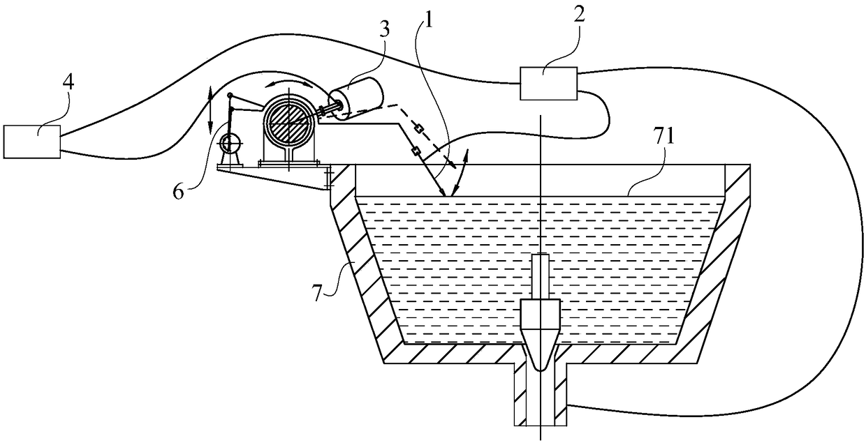
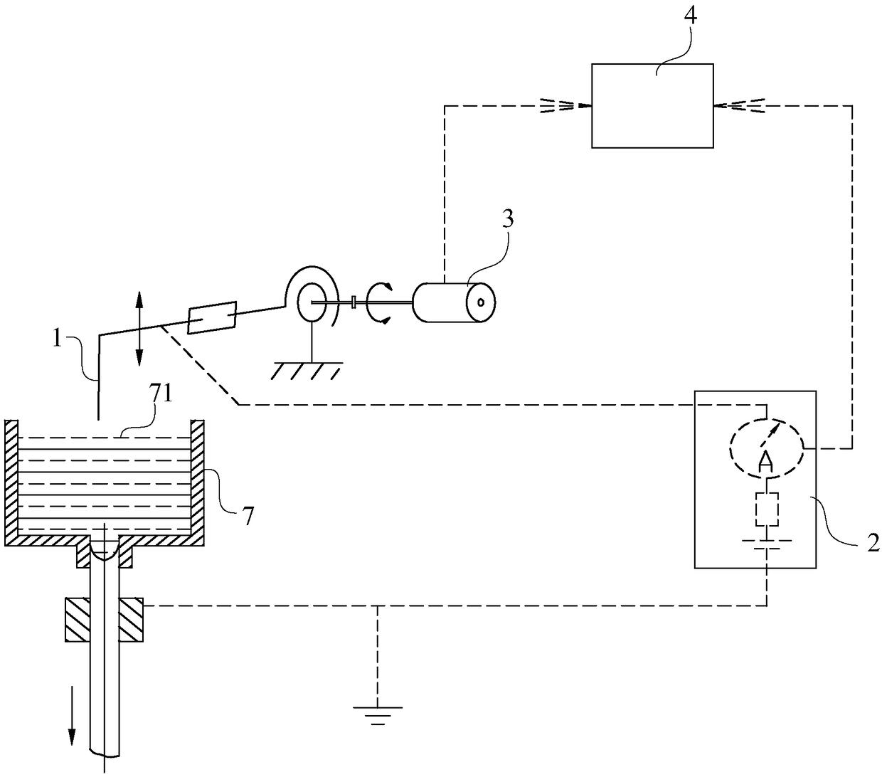
[0055] Please refer to Figure 1 to Figure 3 , this solution provides a liquid level detection device, which is applied to continuous casting equipment 7. The liquid level detection device uses the reciprocating motion of the probe 1 to repeatedly contact and separate from the liquid surface of the metal melt, so as to realize the conduction and disconnection of electrical signals , while recording the displacement of the probe 1 when it is turned on, and the controller 4 processes the displacement when the probe 1 is turned on as the height of the metal liquid level, thereby continuously and accurately measuring the height of the metal liquid level.

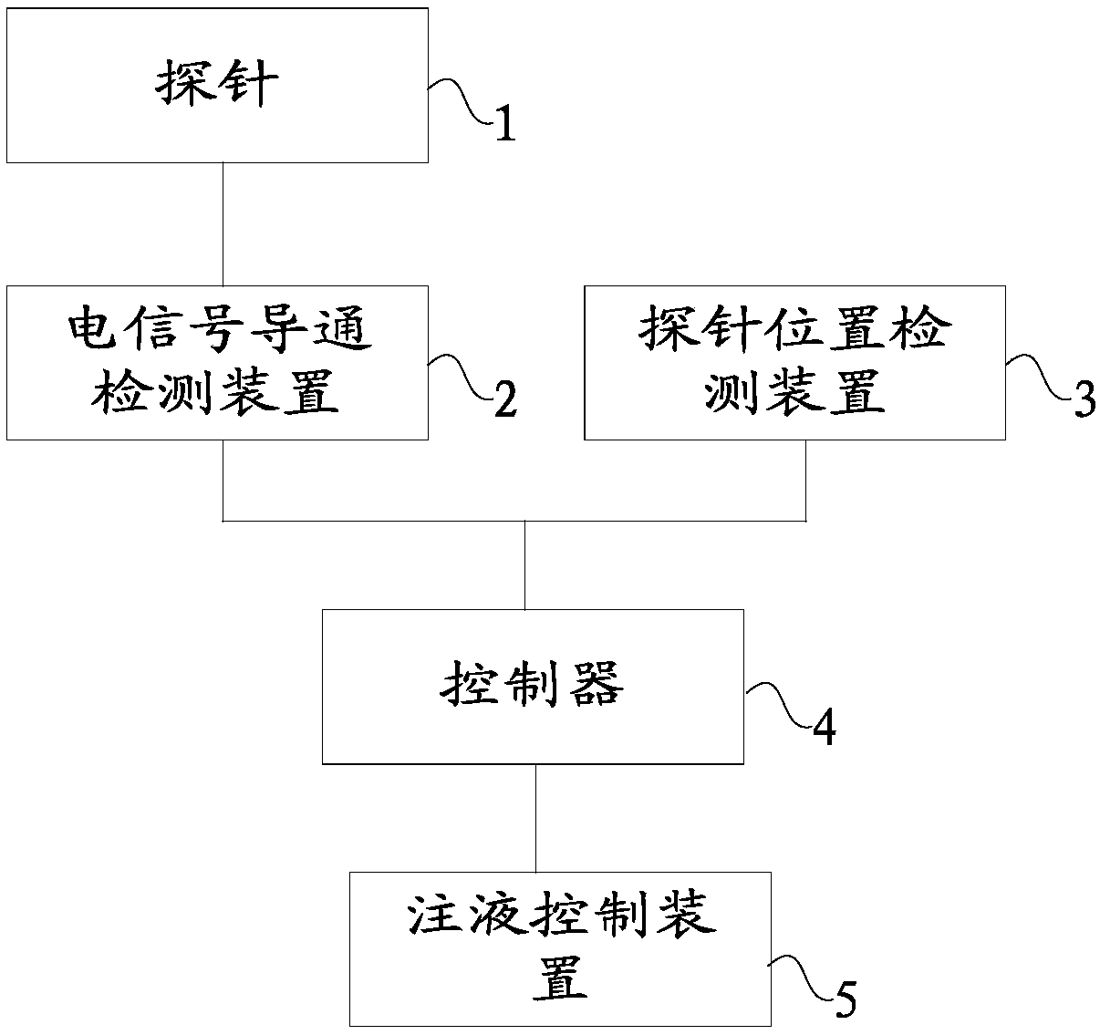
[0056] The liquid level detection device includes a probe 1, a probe movement mechanism 6, a probe position detection device 3, an electric signal conduction detection device 2 and a controller 4, the probe movement mechanism 6 is connected to the probe 1, and the electric signal conduction detection The device 2 is respectively...


PUM


Abstract

The invention discloses a liquid level detection device and a liquid level detection method. The liquid level detection method comprises the following steps that: through a probe movement mechanism, driving a probe to carry out reciprocating motion relative to the liquid level of metal liquid in the liquid storage containing chamber of continuous casting equipment; through a probe position detection device, detecting the displacement information of the probe in real time, and sending the displacement information of the probe to a controller; and at a moment when the probe is in contact with the liquid level of the metal liquid in the liquid storage containing chamber, forming a loop by an electric signal conduction detection device, the probe and the continuous casting equipment, detectingloop conduction information by the electric signal conduction detection device, sending the loop conduction information to the controller, and judging the liquid level height of the metal liquid in the liquid storage containing chamber of the continuous casting equipment according to the loop conduction information and the displacement information of the probe. By use of the liquid level detection method, the liquid level of the metal liquid can be effectively detected so as to guarantee that vertical continuous casting equipment can successfully cast high-quality metal blanks.

Description

technical field [0001] The invention relates to the field of metal blank production, in particular to a liquid level detection device and a liquid level detection method. Background technique [0002] In continuous casting production, the automatic control of the liquid level of the metal solution in a high temperature state can make the metal liquid level in the crystallizer relatively stable, effectively reduce or eliminate surface defects such as coarse grain layer and segregation tumor, and make the surface of the ingot Make it as smooth as possible to reduce defects such as ingot thickness difference and internal shrinkage cavity, and improve the quality of the billet. [0003] The premise of realizing automatic liquid level control is to be able to obtain liquid level height data automatically, continuously, accurately, reliably, and economically, and to perform closed-loop control of the liquid level through the liquid level automatic control system. Therefore, in th...

Claims


Application Information

Patent Timeline
Patent Type & Authority Applications(China)
IPC IPC(8): G01F23/22B22D11/18B22D2/00
CPCG05D9/12G01F23/22B22D11/041B22D11/081B22D11/141B22D11/186
Inventor 陈世雄杨健王振中吴晓东吉晓辉殷春武丹李笃
Owner XIAN METALWK HYDRAUMATIC MACHINERY
Why Eureka
Try Eureka