Milling tool path optimization method for low carbon

A tool path, milling technology, applied in the direction of electrical program control, digital control, etc., to achieve the effect of short processing time

Active Publication Date: 2019-01-18
XI AN JIAOTONG UNIV
View PDF5 Cites 23 Cited by
  • Summary
  • Abstract
  • Description
  • Claims
  • Application Information

AI Technical Summary

Problems solved by technology

It can be seen that the optimization of the tool path can effectively reduce the energy consumption of the machine tool and reduce the carbon emission in the machining process. However, the current research only stays at the stage of exploring the impact of the tool path on th...

Method used


Image

  • Milling tool path optimization method for low carbon
  • Milling tool path optimization method for low carbon
  • Milling tool path optimization method for low carbon

Examples


Embodiment Construction

[0082] In the actual milling process, the length of the tool path affects the processing time. Through path optimization, the actual processing time can be shortened, thereby reducing the consumption of materials and energy in the processing process, and at the same time reducing the generation of waste. There is a direct relationship between the consumption of materials and energy and the amount of waste generated, so route optimization can reduce carbon emissions in the processing process. For the milling of the mold cavity, the machining process often needs to remove a large amount of workpiece material, consumes a lot of electricity, and therefore generates a large amount of carbon emissions. By optimizing the tool path, not only can the processing efficiency of the mold cavity be improved, but at the same time It can also reduce the carbon emissions in the processing process and reduce the processing cost of the enterprise.

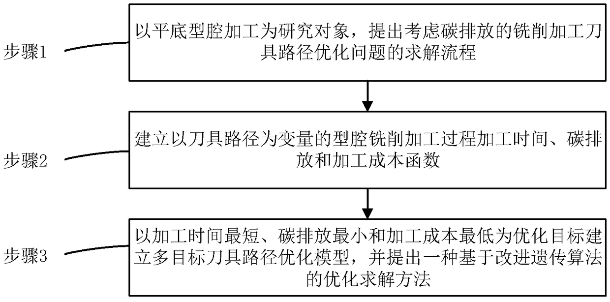
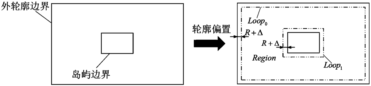
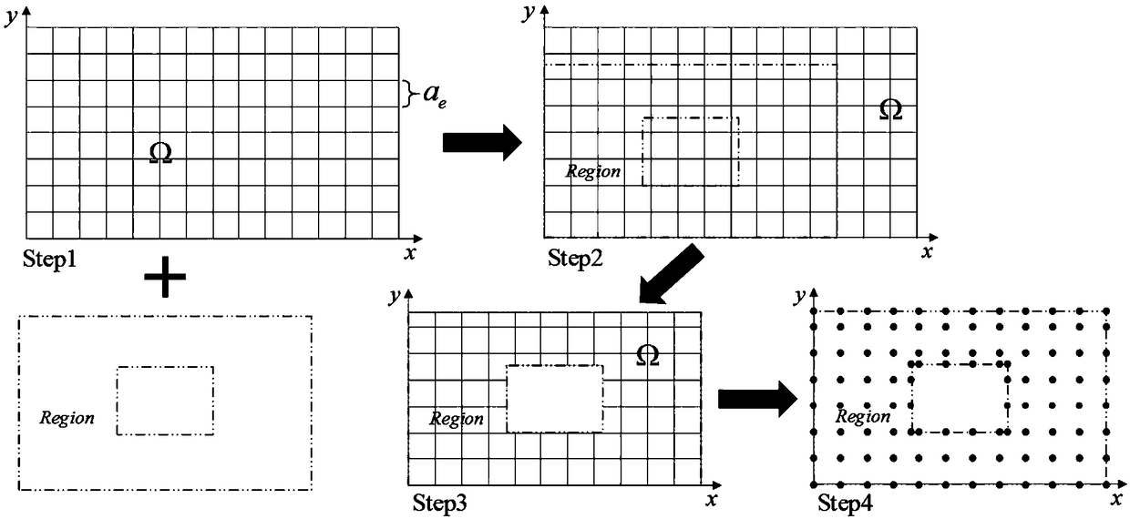
[0083] see figure 1 , the present invention i...


PUM


Abstract

The invention discloses a milling tool path optimization method for low carbon. The milling tool path optimization method comprises the steps of firstly, building solving process of milling tool pathoptimization problem considering carbon emission by taking flat cavity processing as a research object; secondly, building processing time, carbon emission and a processing cost function of cavity milling process taking a tool path as a variable; and finally, building a multi-target tool path optimization model taking shortest processing time, minimum carbon emission and lowest processing as optimization targets, and optimizing the multi-target tool path optimization model by an improved genetic algorithm-based optimization solution method. The method comprehensively considers the targets of the processing time, the carbon emission and the processing cost, the actual application demand of an enterprise is satisfied, the tool path optimization solving process is simple and effective and iseasy to implement, the population convergence speed is rapid during path optimization solving by the proposed improved genetic algorithm, and the algorithm can be effectively prevented from being sunken to local optimal solution.

Description

technical field [0001] The invention belongs to the technical field of advanced manufacturing and automation, and in particular relates to a low-carbon milling tool path optimization method. Background technique [0002] In recent years, with the rapid development of the manufacturing industry, the problems of high energy consumption and high emissions have become increasingly prominent. According to the International Energy Agency (IEA) report: 33% of global energy consumption and 38% of CO 2 Emissions originate from manufacturing. It can be seen that the manufacturing industry has become one of the main sources of energy consumption and carbon emissions today. With the increasing awareness of environmental protection, the issue of energy conservation and environmental protection in the manufacturing industry has attracted widespread attention from scholars and universities at home and abroad, and the low-carbon optimization of mechanical processing has gradually become a...

Claims


Application Information

Patent Timeline
IPC IPC(8): G05B19/19
CPCG05B19/19
Inventor 周光辉张俊杰田长乐何君
Owner XI AN JIAOTONG UNIV
Why Eureka
Try Eureka