
Method for producing radioactive isotopes in a fast neutron reactor

A radionuclide and fast neutron technology, applied in the field of nuclear engineering, can solve the problems of rising product cost, large assembly weight, and reduced capacity, and achieve the effect of reducing materials, reducing weight, and simplifying use

Pending Publication Date: 2019-02-05
JOINT CO SCI & INNOVATIONS
View PDF4 Cites 5 Cited by
  • Summary
  • Abstract
  • Description
  • Claims
  • Application Information

AI Technical Summary

Problems solved by technology

The disadvantage of this method is that the neutron flux is relatively low (usually below 5х10 14 сm -2 the s -1 ), the nuclear reactor containing the target has a small core, and a relatively small amount of "extra" neutrons is used to produce radionuclides due to the small reaction area
[0008] The disadvantages of this method are: the number of targets is small, and the target can be placed in the deceleration element with zirconium hydride control rods; due to the movement of the control rods in the nuclear reactor, the neutron density and energy change during the operation of the reactor, which makes it difficult to calculate the accumulated radioactivity Nuclides have become more difficult; the maximum time required to find control rods in a nuclear reactor can lead to a significant drop in the production of radionuclides due to their radioactive decay
[0011] Disadvantages of the method of radionuclide production considered in the wall tubes of fast neutron nuclear reactors are: the presence of absorbing elements in the radiation assembly, which leads to an increase in the cost of the product, a reduction in the capacity for accommodating targets in the radiation assembly, a reduction in the density of the neutron stream, radiation Increased risk of radiation damage to fuel assemblies surrounding the assembly
[0016] 1) There is a large amount of steel (more than 50%) in the steel component, so the assembly weight is large and the work of the steel component is more complicated;

Method used


Image

  • Method for producing radioactive isotopes in a fast neutron reactor
  • Method for producing radioactive isotopes in a fast neutron reactor

Examples


Embodiment Construction

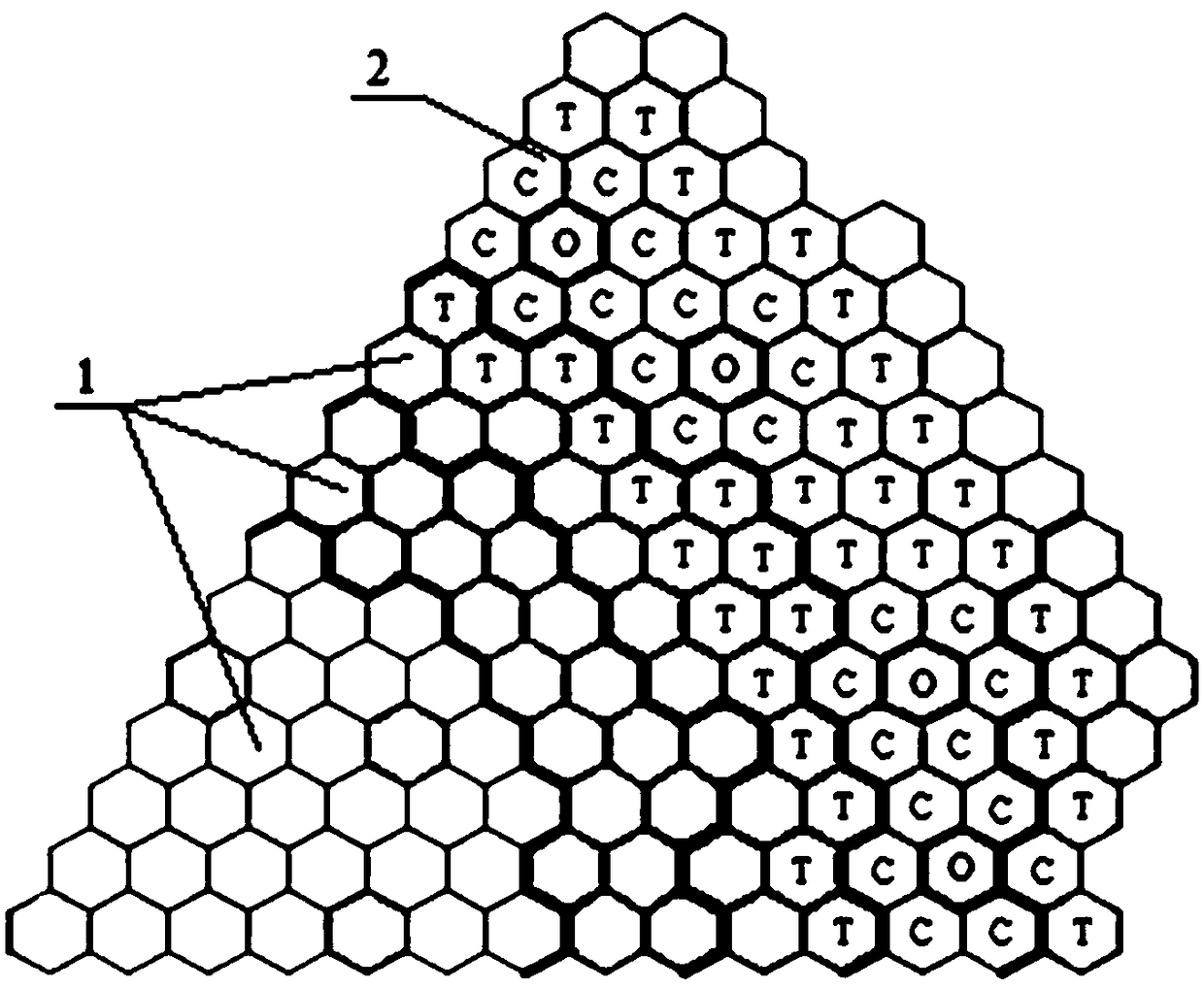
[0032] The method is implemented in a fast neutron reactor, which has an outer shell in which the core 1 and wall tubes 2 are located (see figure 1 ). In the core there are fuel assemblies used to generate the fast neutron flux. Inside the wall tubes of the reactor are the fuel assemblies used to produce plutonium and reduce the neutron flux, preventing the neutron flux from escaping the reactor.

[0033] In order to implement the method according to the invention, a radiant assembly is installed in the wall duct 2, in figure 1 The letter O is used to indicate the radiation component. The radiant assemblies are installed in the fuel assemblies denoted by the letter T and are separated from them by an intermediate steel assembly marked with the letter C, therefore, in order to carry out the invention, the assemblies are installed as follows: the irradiated assemblies are installed in the wall tubes of the reactor, The steel assembly is located around it, and the fuel assem...


PUM


Abstract

The invention relates to nuclear engineering and can be used in the neutron irradiation of different materials (targets) to produce radionuclides. The essence of the invention lies in a method for producing radioactive isotopes in a fast neutron reactor which includes the following steps. Targets for the production of radioisotopes are positioned between sleeves and rods in an irradiation assembly, the rods being made of a neutron-moderating material, and the irradiation assembly is placed in a side shield of a fast neutron reactor. The irradiation assembly is surrounded with assemblies whichdo not contain nuclear fuel. In the irradiation assembly fast neutrons are passed through the neutron-moderating material, and the moderated neutrons are then passed through the material to be irradiated (the target) in the irradiation assembly. The characterizing features of the present invention are that radioisotopes are produced simultaneously in the irradiation assembly and the surrounding assemblies, in which the steel content is not greater than 50%. The targets in the irradiation assembly have an absorption cross section of more than 1 barn at a neutron energy of less than 0.1 MeV. Thetargets in the assemblies surrounding the irradiation assembly have a neutron absorption cross section of less than 1 barn at a neutron energy of more than 0.1 MeV.

Description

technical field [0001] The present invention belongs to nuclear engineering and can be used when irradiating various materials (targets) with neutrons to produce radionuclides. Background technique [0002] There is known a method of irradiating targets with neutrons in nuclear reactors (research nuclear reactors, water-water power (reactor) reactors, high-power tubular (reactor) reactors, etc.), the irradiated material is the target, placed in a special Radiation assemblies (radiation assemblies), which are placed in the core of a nuclear reactor with a specific thermal neutron spectrum. When the reactor is in operation, the target is irradiated with neutrons, in which radionuclides accumulate to achieve the desired activity. [0003] After removing irradiated components from a nuclear reactor, dismantle the target in a radiation-shielded chamber or box. Extract radioactive cores from radionuclides. The radioactive core is then placed in a protective (protective) contain...

Claims


Application Information

Patent Timeline
IPC IPC(8): G21G1/02G21G4/08G21C1/02
CPCG21C1/02G21G1/02G21G1/08Y02E30/30G21G4/08G21G1/00
Inventor V·D·里索瓦尼A·V·杜比N·A·康德拉夫V·A·珀舒科夫V·G·阿斯莫洛夫M·V·巴卡诺夫E·A·科茨马诺夫B·A·瓦西勒夫D·A·克里诺夫B·G·西林
Owner JOINT CO SCI & INNOVATIONS
Learn More