Spraying tower waste gas purification and recycling device

A technology of exhaust gas purification and recovery device, applied in combination devices, chemical instruments and methods, dispersed particle separation and other directions, can solve the problems of costing a lot of energy, reducing the total amount of exhaust gas emissions, energy waste, etc., to achieve waste heat recovery and utilization, The effect of saving heating time and energy

Pending Publication Date: 2019-02-15
广东联和环保科技有限公司
View PDF0 Cites 0 Cited by
  • Summary
  • Abstract
  • Description
  • Claims
  • Application Information

AI Technical Summary

Problems solved by technology

[0002] In the production of chemical dyes, the dye slurry is spray-dried in the drying spray tower. The hot air used to dry the slurry flows out from the bottom of the tower. The hot air carries a large amount of dry dye powder. Generally, a cyclone separator is used to remove dust, The bag filter then uses a water film filter to remove dust and then empty it. This kind of dust treatment method, firstly, the condensed liquid cannot be recycled, and it takes a lot of energy to deal with it; secondly, the hot air carries a lot of heat and has not been effectively used. , resulting in a waste of energy. Once again, the waste gas from chemical production should be recycled as much as possible after being purified to meet the standard to reduce the total amount of waste gas emissions.

Method used


Image

  • Spraying tower waste gas purification and recycling device

Examples


Embodiment Construction

[0017] The accompanying drawings are for illustrative purposes only, and should not be construed as limitations on this patent; in order to better illustrate this embodiment, certain components in the accompanying drawings will be omitted, enlarged or reduced, and do not represent the size of the actual product; for those skilled in the art It is understandable that some well-known structures and descriptions thereof may be omitted in the drawings. The positional relationship described in the drawings is for illustrative purposes only, and should not be construed as a limitation on this patent.

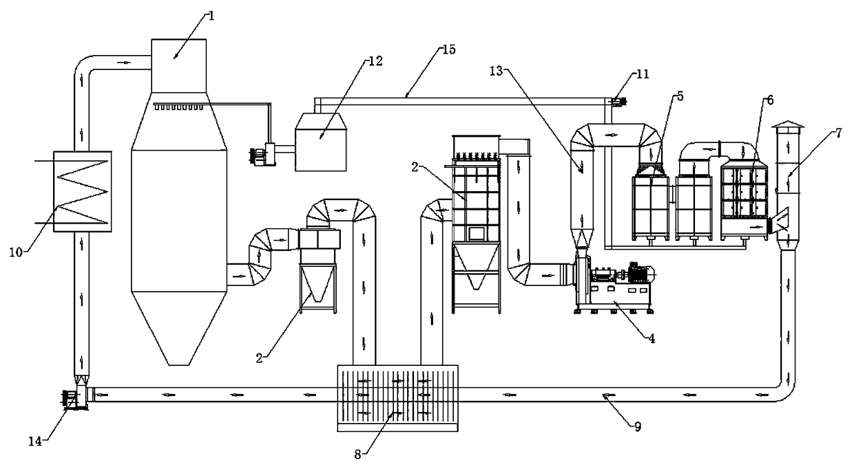
[0018] Such as figure 1 As shown, the spray tower exhaust gas purification and recovery device mainly includes: chemical spray tower 1, cyclone dust removal device 2, bag dust removal device 3, induced draft fan 4, washing condensation adsorption tower 5, secondary UV electric field purifier 6, exhaust gas discharge pipe 7 , the bottom of the chemical spray tower 1 is connected to th...


PUM


Abstract

The invention relates to the technical field of waste gas purification and recycling and relates to a spraying tower waste gas purification and recycling device. The bottom of a chemical spraying tower is connected with a cyclone dust collection device; a waste heat recycling device is arranged between the cyclone dust collection device and a cloth bag dust collection device; the top of the wasteheat recycling device is connected with a cloth bag dust collector; the air outlet of the cloth bag dust collector is connected with one end of a draft fan; the other end of the draft fan is connectedwith a washing condensation absorption tower and a secondary UV (Ultraviolet) electric field purifier in sequence; the secondary UV electric field purifier is connected with a waste gas discharge tube and a recycling pipeline; and the recycling pipeline penetrates through the waste heat recycling device and a heater in sequence and is connected with the top of the chemical spraying tower. Compared with the prior art, the device has the beneficial effects that a backflow air flow has a high temperature, the air flow heating time and energy can be saved, moisture generated in the purification process is discharged into a material stirrer from a condensation accumulated liquid backflow tube, and thus accumulated liquid condensation, waste gas purification and cyclic utilization of production waste gases and waste heat can be achieved.

Description

technical field [0001] The invention relates to the technical field of waste gas purification and recovery, and more specifically, to a spray tower waste gas purification and recovery device. Background technique [0002] In the production of chemical dyes, the dye slurry is spray-dried in the drying spray tower. The hot air used to dry the slurry flows out from the bottom of the tower. The hot air carries a large amount of dry dye powder. Generally, a cyclone separator is used to remove dust, The bag filter then uses a water film filter to remove dust and then empty it. This kind of dust treatment method, firstly, the condensed liquid cannot be recycled, and it takes a lot of energy to deal with it; secondly, the hot air carries a lot of heat and has not been effectively used. , resulting in a waste of energy. Once again, the waste gas from chemical production should be recycled as much as possible after being purified to meet the standard, so as to reduce the total amount ...

Claims


Application Information

Patent Timeline
IPC IPC(8): B01D50/00
CPCB01D50/00
Inventor 苟亚松
Owner 广东联和环保科技有限公司
Why Eureka
Try Eureka