Water-in-oil demulsification method for oil field

A water-in-oil emulsion and water-in-oil technology, which is applied in the fields of hydrocarbon oil dehydration/demulsification, dehydration/demulsification by chemical method, dehydration/demulsification by mechanical method, etc. Problems such as limited effect, increased water content and total liquid volume

Pending Publication Date: 2019-02-15
XIAN TIANXIANG ENERGY TECH
View PDF2 Cites 8 Cited by
  • Summary
  • Abstract
  • Description
  • Claims
  • Application Information

AI Technical Summary

Problems solved by technology

On the one hand, the amount of produced fluid and sewage treatment has increased sharply, some process equipment in the gathering and transportation system cannot meet the production requirements, and the water content and total liquid volume of the heated crude oil during the crude oil gathering and transportation process have increased, resulting in a substantial increase in production energy consumption On the other hand, due to the promotion and application of tertiary oil recovery technology and the development of high-viscosity and high-viscosity crude oil, the difficulty of oil and water separation has increased
In addition, with the development and production of oilfields, the original separators in each station cannot adapt to actual changes due to their design conditions and operating parameters, and the upstream fluid emulsification (W / O) is serious. However, due to the short reaction time between the agent and crude oil and the fact that the heating temperature of the upstream heating furnace cannot be kept above the specified temperature (less than 35°C), the effect of chemical demulsification is very limited, resulting in separation on the station The equipment cannot achieve effective oil and water separation, which adds difficulty and pressure to the oil-water separation of downstream stations
Although the addition of demulsifier is increased, the demulsification effect is very limited, and the excessive increase of the dosage does not meet the environmental protection requirements.

Method used


Image

  • Water-in-oil demulsification method for oil field
  • Water-in-oil demulsification method for oil field

Examples


Embodiment 1

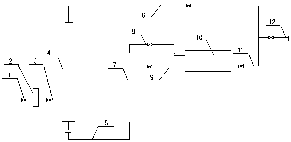
[0018] Such as figure 1 Shown, a kind of method for the water-in-oil demulsification of oilfield; It is characterized in that: comprise at least, filter 2, stabilizer 4, cyclone demulsifier 7, coalescing demulsifier 10; After the emulsion is filtered from the liquid inlet pipe 1 through the filter 2 to remove impurities in the liquid, it enters the flow stabilizer 4 through the connecting pipeline 3, and the water-in-oil emulsion is stabilized, buffered, and gas-liquid separated through the flow stabilizer 4. The associated gas enters the gas pipeline 6 at the top of the flow stabilizer 4 and is output; the separated oil-water enters the bottom inlet of the cyclone demulsifier 7 through the emulsified oil-water pipeline 5; , through the cyclone demulsifier 7, the oil outlet pipeline 8 and the oily sewage outlet pipe 9 respectively enter the coalescing demulsifier 10, and after the coalescing demulsifier 10 performs rectification and demulsification, the water-in-oil emulsion i...


PUM


Abstract

The invention relates to equipment applied to the oil and gas industry, wastewater treatment industry and the like, and in particular relates to a water-in-oil demulsification method for an oil field.The equipment is characterized by at least comprising a filter, a flow stabilizer, a cyclone emulsion breaker and a coalescing emulsion breaker. The method comprises the following steps: enabling water-in-oil emulsion to pass through a filter from a liquid inlet pipe, filtering impurities in the liquid, enabling the emulsion to enter the flow stabilizer via a connecting pipeline, stabilizing andbuffering the water-in-oil emulsion by the flow stabilizer, performing gas-liquid separation, and enabling the separated associated gas to enter a gas pipeline on the top of the flow stabilizer to output; enabling the separated oil water to enter the bottom inlet of the cyclone emulsion breaker via an emulsified oil water connecting pipeline; making a high-speed cyclone motion inside the cyclone emulsion breaker, enabling the emulsion to respectively enter the coalescing emulsion breaker via the oil outlet pipeline of the cyclone emulsion breaker and an oily wastewater outlet pipe, performingrectifier demulsification by the coalescing emulsion breaker, decomposing the water-in-oil emulsion into water and oil for the second time, gathering the decomposed water and oil to an oil-water mixing pipeline, merging with the gas pipeline, delivering to a separation device via a gas-liquid mixing pipeline so as to perform oil-water separation, thereby realizing oil and water demulsification.

Description

technical field [0001] The invention relates to equipment used in the oil and gas industry and sewage treatment industry, in particular to a water-in-oil demulsification method used in oil fields. Background technique [0002] As most of my country's oil fields gradually enter the middle and late stages of exploitation, the water content of crude oil continues to increase. On the one hand, the amount of produced fluid and sewage treatment has increased sharply, some process equipment in the gathering and transportation system cannot meet the production requirements, and the water content and total liquid volume of the heated crude oil during the crude oil gathering and transportation process have increased, resulting in a substantial increase in production energy consumption ; On the other hand, due to the promotion and application of tertiary oil recovery technology and the development of high-viscosity and high-viscosity crude oil, the difficulty of oil and water separatio...

Claims


Application Information

Patent Timeline
Patent Type & Authority Applications(China)
IPC IPC(8): C10G33/00C10G33/04C10G33/06
CPCC10G33/00C10G33/04C10G33/06
Inventor 何涛杜彦甫
Owner XIAN TIANXIANG ENERGY TECH
Why Eureka
Try Eureka