Tubular LPCVD (Low Pressure Chemical Vapor Deposition) vacuum reaction chamber

A reaction chamber and vacuum technology, applied in the direction of gaseous chemical plating, crystal growth, coating, etc., can solve the problems of unstable air flow, easy aging of sealing ring, deposition rate, inconsistent film performance, etc., and reduce the temperature of sealing surface , Excellent sealing performance, shortening maintenance time

Active Publication Date: 2019-02-15
HUNAN RED SUN PHOTOELECTRICITY SCI & TECH
View PDF5 Cites 11 Cited by
  • Summary
  • Abstract
  • Description
  • Claims
  • Application Information

AI Technical Summary

Problems solved by technology

[0003] At present, the vacuum reaction chamber is a single-layer quartz tube. First, when the polysilicon film is deposited on the inner wall of the single-layer quartz tube to a certain thickness, when there is a sudden power failure or cooling maintenance, the inner wall of the quartz tube is covered with polysilicon. Cracks will occur, making the quartz tube scrapped, the service life of the quartz tube is very low, and it is extremely cumbersome to replace the quartz tube, and the reaction chamber needs to be re-sealed and installed
Secondly, the single-layer quartz tube adopts single-layer water-cooled flanges before ...

Method used


Image

  • Tubular LPCVD (Low Pressure Chemical Vapor Deposition) vacuum reaction chamber
  • Tubular LPCVD (Low Pressure Chemical Vapor Deposition) vacuum reaction chamber
  • Tubular LPCVD (Low Pressure Chemical Vapor Deposition) vacuum reaction chamber

Examples


Embodiment Construction

[0026] The present invention will be described in further detail below in conjunction with the accompanying drawings and specific embodiments.

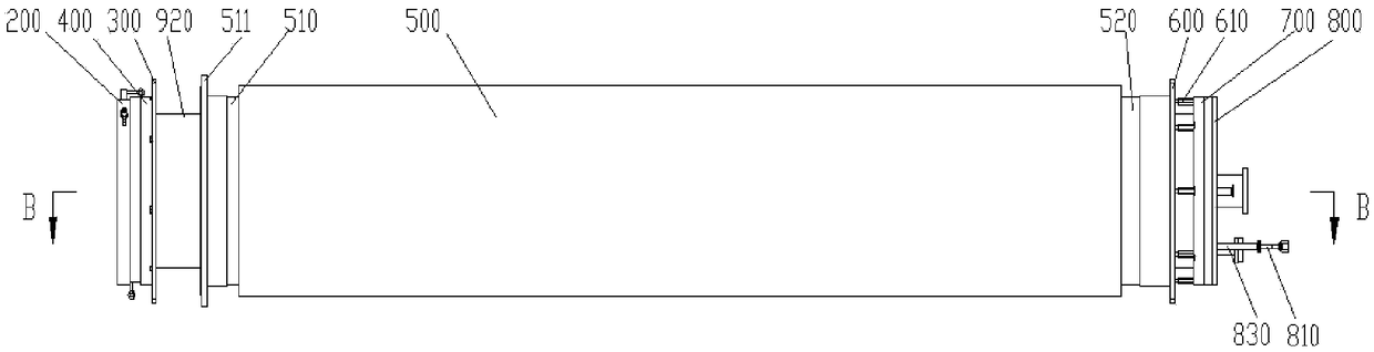
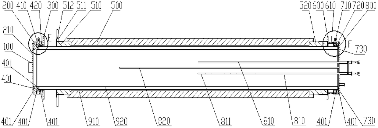
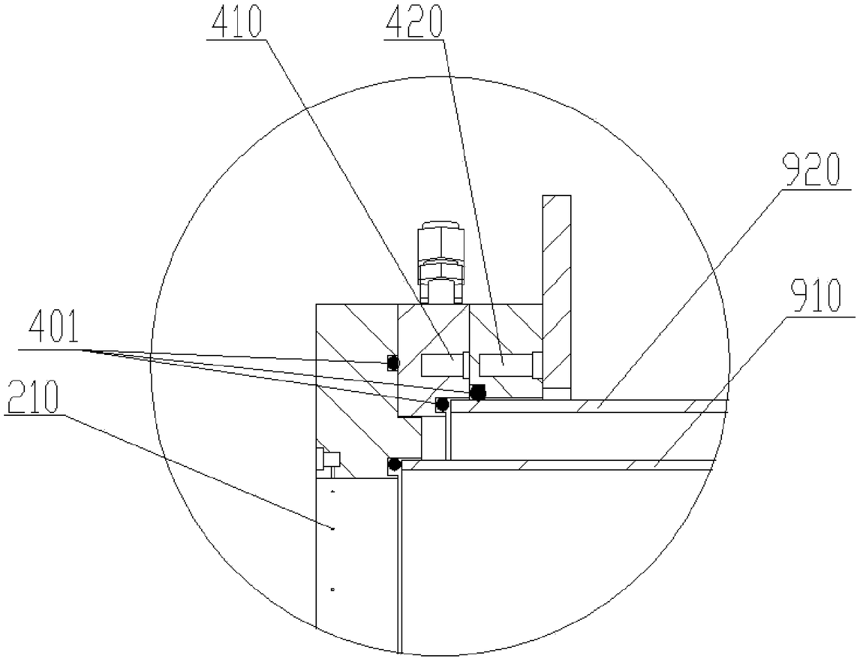
[0027] Such as Figure 1 to Figure 4 As shown, the tubular LPCVD vacuum reaction chamber of this embodiment includes a furnace door 100, a front flange 200, a front support flange 300, a front sealing assembly 400, a heating furnace body 500, a rear support flange 600, and a rear sealing assembly 700. , the tail end flange 800, the inner layer quartz tube 910 and the outer layer quartz tube 920, the outer layer quartz tube 920 is set on the outside of the inner layer quartz tube 910, the heating furnace body 500 is set on the outer layer quartz tube 920, the front support method The flange 300 and the rear support flange 600 are respectively located on the outer tube wall at the two ends of the outer layer quartz tube 920, the furnace door 100 is connected with the front end flange 200, and the front end flange 200 covers the inner la...


PUM


Abstract

The invention discloses a tubular LPCVD (Low Pressure Chemical Vapor Deposition) vacuum reaction chamber. The tubular LPCVD vacuum reaction chamber comprises a furnace door, a front flange, a front support flange, a front sealing assembly, a heating furnace body, a back support flange, a back sealing assembly, an end flange, an inner quartz tube and an outer quartz tube, wherein the heating furnace body sleeves the outer quartz tube, the front support flange and the back support flange are respectively located on the outer tube wall of both ends of the outer quartz tube, the front support flange, the heating furnace body and the back support flange are fixedly arranged, the furnace door is connected with the front flange, the front flange covers the front end openings of the inner and outer quartz tubes, the front flange is connected with the outer quartz tube by virtue of the front sealing assembly, the front sealing assembly is fixed to the front support flange, the end flange is arranged on the back ends of the inner and outer quartz tubes, the end flange is connected with the outer and inner quartz tubes by virtue of the back sealing assembly, and the back sealing assembly is fixed to the back support flange. The tubular LPCVD vacuum reaction chamber has the advantages of simplicity and rapidity in disassembly and maintenance and obvious economic benefits, and the maintenance time is shortened.

Description

technical field [0001] The invention relates to LPCVD (low-pressure chemical vapor deposition) equipment, in particular to a tube-type LPCVD vacuum reaction chamber. Background technique [0002] LPCVD (Low Pressure Chemical Vapor Deposition, Low Pressure Chemical Vapor Deposition) equipment is a chemical vapor deposition (CVD) equipment that generates a solid reactant through a chemical reaction of a mixed gas under low pressure and high temperature conditions and deposits it on the surface of a silicon wafer to form a thin film. One of them is mainly used in industries such as integrated circuits, power electronics, photovoltaics, and micro-electromechanical systems. In the photovoltaic industry, LPCVD is mainly used in the growth and deposition of polysilicon, amorphous silicon, SiO2, Si3N4, phosphosilicate glass (PSG) and boron-doped phosphosilicate glass (BPSG) and other thin films. As a kind of CVD equipment, its most important function or ultimate goal is still CVD r...

Claims


Application Information

Patent Timeline
IPC IPC(8): C23C16/44C23C16/455C30B29/06C30B28/14
CPCC23C16/44C23C16/4409C23C16/455C30B28/14C30B29/06
Inventor 李明吴德轶张弥涛成秋云张春成
Owner HUNAN RED SUN PHOTOELECTRICITY SCI & TECH
Why Eureka
Try Eureka