

Apparatus and method for detecting sealing performance of battery system cabinet
A technology of battery system and sealing performance, which is applied in the test of fluid tightness, by detecting the appearance of fluid at the leakage point, and by measuring the increase and deceleration rate of the fluid, etc., which can solve the problems of inability to judge quantitatively, hidden dangers of hydrogen safety, and low precision, etc. problem, to achieve the results of true, accurate and reliable leak detection, to ensure the quantitative accuracy of calibration leak detection, and to eliminate the effect of misjudgment
Pending Publication Date: 2019-02-19
CHINA AUTOMOTIVE BATTERY RES INST CO LTD
View PDF5 Cites 19 Cited by
- Summary
- Abstract
- Description
- Claims
- Application Information
AI Technical Summary
Problems solved by technology
This method is to observe whether there are air bubbles in the battery system box immersed in the water tank with human eyes. This method is not accurate and cannot be quantitatively judged, and the battery system will be immersed in water. There will be dangers of short circuit, fire, and explosion.
[0006] (2) The pressure decay method uses a mixture of hydrogen and nitrogen as the tracer gas, which is prone to hydrogen embrittlement of the sample, and the use of hydrogen has potential safety hazards
[0007] (3) The ultrasonic leak detection method is not easy to find the leaks and pores of complex workpieces, nor is it suitable for finding leaks and pores of assembled workpieces
Since helium is sprayed in the atmospheric environment, and there is air inside the sample, there is a helium background. For the battery system box with high sealing requirements, because the internal and external pressures are equal, the helium sprayed outside is not easy to enter the sample, so The detection accuracy is not high
[0010] (6) The vacuum helium hood method is to put the sample into a helium hood filled with helium gas. Generally, the helium hood is made of soft material, and the overall leak rate can be tested, but the location of the leak point cannot be determined.
This invention also utilizes the air pressure difference and pressure change, because the temperature of the air is easily affected by light and heat sources, so the measurement accuracy is not high
Method used
View moreImage
Smart ImageViewing Examples

Examples
Embodiment
[0081] The test sample in this embodiment is a power battery system for new energy vehicles, the upper shell is made of non-metallic carbon fiber SMC material, and the lower shell is made of cold-rolled steel plate DC01. Generally speaking, the pressure that determines the pressure of the battery pack box in the tightness test is determined by the pressure difference that can be tolerated by its upper case.
Login to View More PUM
 Abstract
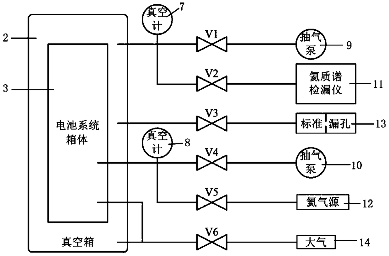
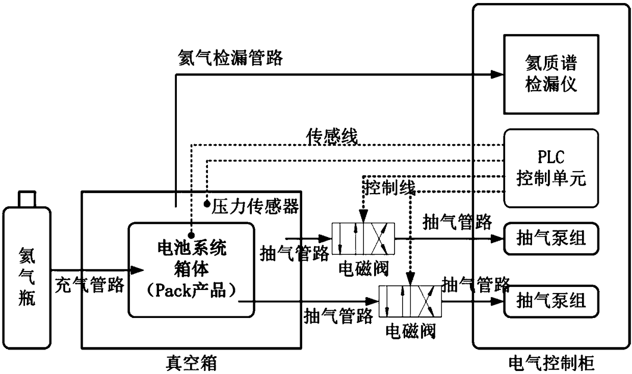
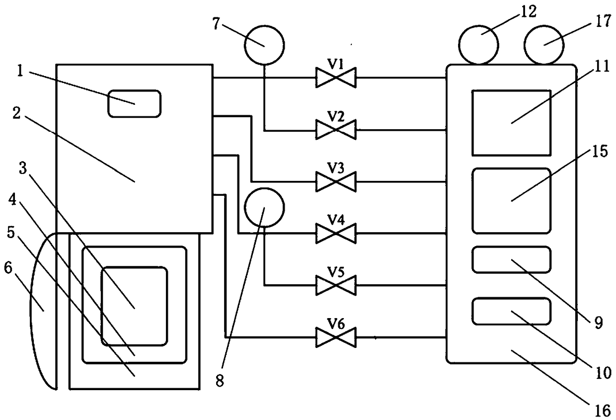
The invention discloses an apparatus and a method for detecting the sealing performance of a battery system box, comprising: a vacuum box, a helium mass spectrometer leak detector, two sets of suctionpumps, and a helium source. The battery system cabinet is arranged in the vacuum box during testing. The helium mass spectrometer leak detector is connected to the vacuum box through the leak detection pipeline. One of the two sets of suction pumps is connected to the vacuum box through the suction line, and the other set is connected to the battery system box through the suction line. The battery system cabinet is connected to the external helium source through the supply line. The battery system cabinet and the vacuum box are respectively connected to the atmosphere through a bleed valve and a relief valve. Pressure sensors are respectively arranged outside the vacuum box and the battery system box. The two pressure sensors are respectively connected to the PLC control unit. The vacuumbox is connected to a standard leak, which is used to calibrate the device. Each pipeline is provided with a solenoid valve, and each solenoid valve is controlled by a PLC control unit. The device cansafely and efficiently detect the sealing performance of the battery system cabinet, and the test accuracy is high.
Description
technical field [0001] The invention relates to a device and method for detecting the sealing performance of a battery system box, which is mainly used for the detection or testing of the sealing performance of a vehicle-mounted power battery pack or a system box of a new energy vehicle. Background technique [0002] At present, in the new energy vehicle industry, the sealing level of the on-board power battery system must at least meet the protection level of IP67 and above, where "6" means dust tight, that is, no dust is allowed to enter; "7" means short-term water immersion performance, that is, meets Soak in water for 30 minutes without leakage. [0003] At present, battery manufacturers are mainly worried that liquid water will enter the battery pack during the operation of the vehicle on rainy days or when there is deep water on the road, thereby causing safety hazards such as leakage; or they are worried that water vapor will enter the battery inside the battery syste...
Claims
Login to View More Application Information
Patent Timeline
 Patent Type & AuthorityApplications(China)
IPC IPC(8): G01M3/20G01M3/32
CPCG01M3/202G01M3/226G01M3/3272
Inventor张潇华唐玲邹春龙苏立昌郝宏亮
OwnerCHINA AUTOMOTIVE BATTERY RES INST CO LTD