
Organic electroluminescent device

An electroluminescent device, organic technology, applied in the direction of electro-solid devices, electrical components, semiconductor devices, etc., can solve the problem of low luminous efficiency, and achieve the effect of good hole transport performance

Inactive Publication Date: 2019-02-19
CHANGCHUN HYPERIONS TECH CO LTD
View PDF0 Cites 3 Cited by
  • Summary
  • Abstract
  • Description
  • Claims
  • Application Information

AI Technical Summary

Problems solved by technology

[0005] Purpose of the invention: In view of the above problems, the purpose of the present invention is to provide an organic electroluminescent device, which solves the problem of low luminous efficiency of the current organic electroluminescent device

Method used


Image

  • Organic electroluminescent device
  • Organic electroluminescent device
  • Organic electroluminescent device

Examples


Embodiment 1

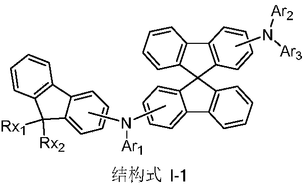
[0149] Synthesis Example 1: Preparation of Compound I-1

[0150]

[0151] Under argon protection, 2,2'-diiodo-9,9'-spirobifluorene (17.6g, 31mmol), compound E1 (8.85g, 31mmol), sodium tert-butoxide (2.98g, 31mmol), bis(triphenylphosphine)palladium(II) dichloride (0.5g, 0.71mmol) and xylene (500ml) were reacted at 130°C for 24 hours. After cooling, water (1000ml) was added, the mixture was filtered, the filtrate was extracted with toluene, and the organic phase was dried over anhydrous magnesium sulfate. This was concentrated under reduced pressure, and the resulting crude product was column-purified, recrystallized from toluene, filtered, and dried to obtain an intermediate Sub-1 (13.5 g, 60%).

[0152] Under argon protection, intermediate Sub-1 (7.26g, 10mmol), compound F1 (1.69g, 10mmol), sodium tert-butoxide (1.3g, 13.5mmol), tris(dibenzylideneacetone) were added to the flask ) Dipalladium (0.046g, 0.05mmol), tri-tert-butylphosphine (0.021g, 0.1mmol) and dehydrated tol...

Embodiment 2

[0153] Synthesis Example 2: Preparation of Compound 1-3

[0154]

[0155] During the preparation of compound I-1 in Synthesis Example 1, compound F1 was replaced by equimolar compound F2, and other steps were the same to obtain compound I-3 (5.75 g, 70%). Mass spectrum m / z: theoretical value: 919.18; found value: 918.35. Theoretical element content (%)C 70 h 50 N 2 : C, 91.47; H, 5.48; N, 3.05; Measured element content (%): C, 91.44; H, 5.54; N, 3.02. The above results confirmed that the obtained product was the target product.

Embodiment 3

[0156] Synthesis Example 3: Preparation of Compound I-13

[0157]

[0158] During the preparation of compound I-1 in Synthesis Example 1, compound F1 was replaced by equimolar compound F3, and other steps were the same to obtain compound I-13 (5.98 g, 69%). Mass spectrum m / z: theoretical value: 867.11; found value: 866.37. Theoretical element content (%)C 66 h 46 N 2 : C, 91.42; H, 5.35; N, 3.23; Measured element content (%): C, 91.40; H, 5.39; N, 3.21. The above results confirmed that the obtained product was the target product.


PUM


Abstract

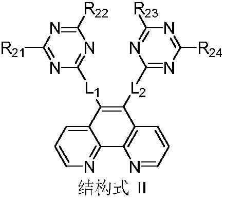
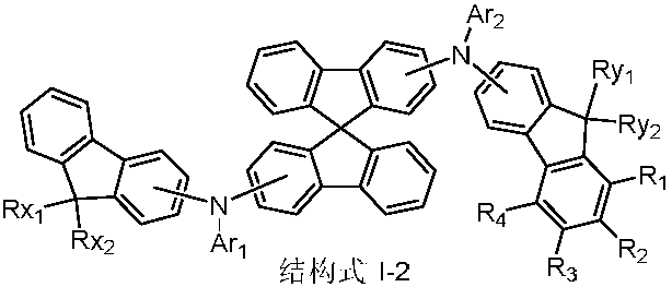
The invention relates to the technical field of organic electroluminescent display and discloses an organic electroluminescent device. The organic electroluminescent device comprises an anode, an organic layer and a cathode layer, and the organic layer is positioned between the anode and the cathode and comprises a hole transmission layer and an electron transmission layer. The hole transmission layer contains a spirobifluorene derivative in a structural formula I-1 as shown in the specification, and the electron transmission layer contains a compound in a structural formula II as shown in thespecification. Due to equivalence of hole transmission performances of the spirobifluorene derivative to electron transmission performances of a phenanthroline derivative, balance in hole and electron transmission is achieved, effective combination in a light-emitting layer can be realized, the carrier utilization rate is increased, and effective light emitting of the device is realized. In addition, the organic electroluminescent device has advantages of low drive voltage, high luminance, high light emitting efficiency and long service life.

Description

technical field [0001] The invention relates to the technical field of organic electroluminescence display, in particular to an organic electroluminescence device. Background technique [0002] Organic Light-Emitting Diode (OLED) refers to a device in which organic photoelectric materials emit light under the action of current or electric field, which can directly convert electrical energy into light energy. In recent years, organic electroluminescent devices are receiving more and more attention as a new generation of flat panel display and solid-state lighting technology. Compared with liquid crystal display technology, organic electroluminescent devices are more and more used in the field of display and lighting due to their low power consumption, active light emission, fast response speed, high contrast, no viewing angle limitation, and flexible display. . [0003] Generally, an organic electroluminescent device has a multilayer structure, including an anode, a cathode...

Claims


Application Information

Patent Timeline
Patent Type & Authority Applications(China)
IPC IPC(8): H01L51/54H01L51/50H01L51/52
CPCH10K85/633H10K50/15H10K50/858
Inventor 蔡辉
Owner CHANGCHUN HYPERIONS TECH CO LTD
Learn More