High pressure self-compensation mechanism of water injection well pulse generator

A pulse generator and self-compensation technology, applied in the field of pressure compensation, can solve problems such as internal and external pressure imbalance, bearing impact, small space, etc., and achieve the effect of improving work reliability and reducing the pressure bearing of the sealing ring

Pending Publication Date: 2019-02-22
CHINA PETROLEUM & CHEM CORP +1
View PDF1 Cites 3 Cited by
  • Summary
  • Abstract
  • Description
  • Claims
  • Application Information

AI Technical Summary

Problems solved by technology

[0004] In the water injection well, the water flow is small and the space is small, so it is impossible to rely on the driving turbine to form effective power. It needs to be driven by a motor. The power output by the motor passes through the reducer, magnetic coupling, and drive shaft to drive the pulse valve to rotate, thereby forming a pressure pulse. , the entire drive system works in the sealed oil chamber, the drive shaft is subjected to the axial hydraulic impact transmitted by the pulse valve, the bearing needs to be lubricated in a high temperature environment, and the hydraulic oil chamber forms a high pressure due to high temperature expansion, which is easy to form a large pressure difference with the water environment. At the same time, the external water flow will also cause impact on bearings and other components, and the imbalance of internal and external pressure will lead to the failure of the seal leakage and affect the working life of the downhole pulse generator. To solve the above problems, a high-pressure self-compensation mechanism for the pulse generator of the water injection well is designed.

Method used


Image

  • High pressure self-compensation mechanism of water injection well pulse generator

Examples


Embodiment Construction

[0021] The detailed description and technical content of the present invention are described below with the drawings, but the drawings are only for reference and description, and are not used to limit the present invention.

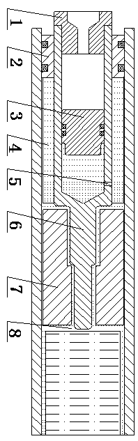
[0022] as attached figure 1 As shown, the high-pressure self-compensation mechanism of the pulse generator of the water injection well includes a cavity, an intermediate body, and a plugging body. The cavity is a sealed oil cavity 8, and the intermediate body is a hollow drive spindle 6. The plugging body It is a floating piston 3, the lower end of the hollow drive spindle 6 is immersed in the seal oil cavity, and a pressure self-compensating channel 5 is left in the radial direction to communicate with the seal oil cavity 8, and the cavity of the seal oil cavity 8 is sealed oil cavity, the center of the hollow drive spindle 6 is provided with a piston cavity, and a floating piston 3 is installed in the piston cavity, and the hollow drive spindle is provi...


PUM


Abstract

The invention discloses a high pressure self-compensation mechanism of a water injection well pulse generator. The high pressure self-compensation mechanism comprises a cavity, a middle body and a sealing and plugging body, wherein the cavity is a sealed oil cavity; the middle body is a hollow driving main shaft; the sealing and plugging body is a floating piston; a sealed oil cavity is formed inthe cavity of the sealed oil cavity; a piston cavity is formed in the center of the hollow driving main shaft; a floating piston is arranged in the piston cavity; a pressure self-compensation passageis formed in the radial direction of the hollow driving main shaft; one end of the pressure self-compensation passage communicates with the piston cavity; the other end of the pressure self-compensation passage communicates with the sealed oil cavity; and the diameter of the pressure self-compensation passage is smaller than the diameter of the piston cavity. The high pressure self-compensation mechanism has the advantages that in the work process of a driving system, pressure compensation is performed in a self-adaptive way through the volume of a hydraulic oil cavity; the one-way pressure bearing stress state of a sealing element is improved; the impact force of environment fluid is balanced; meanwhile, components such as inside bearings can be lubricated; and the work reliability of thepulse generator is improved.

Description

technical field [0001] The invention relates to a pressure compensation technology of a pulse generator in an oil field water injection process, in particular to a high-pressure self-compensation mechanism for a pulse generator of a water injection well. Background technique [0002] In the process of oilfield water injection development, in order to obtain the water injection volume of each water injection layer downhole, it is necessary to lift and release flowmeters at the wellhead for layered testing. With the advancement of electromechanical integration technology and intelligent injection-production control technology, simple and easy technical requirements have been put forward for layered testing technology. For this reason, the research on downhole pressure pulse signal transmission technology has been carried out, and the downhole pulse generator will be used to collect The stratified flow data are transmitted to the wellhead through pressure waves. The pulse gene...

Claims


Application Information

Patent Timeline
Patent Type & Authority Applications(China)
IPC IPC(8): E21B47/18
CPCE21B47/18
Inventor 王增林马珍福崔玉海孙金峰张凯唐高峰刘晋伟王宏万李永康张卫卫
Owner CHINA PETROLEUM & CHEM CORP
Why Eureka
Try Eureka