
Method for overcoming casting bolt shrinkage porosity defect

A technology for castings and bolts, applied in the directions of casting molds, casting mold components, casting molding equipment, etc., can solve the problems of difficulty, increase casting cost, and high cost, and achieve the effect of reducing quality, reducing casting cost, and low free phenol.

Active Publication Date: 2019-03-01
西峡飞龙特种铸造有限公司
View PDF8 Cites 1 Cited by
  • Summary
  • Abstract
  • Description
  • Claims
  • Application Information

AI Technical Summary

Problems solved by technology

However, the method of fixing the cold iron is used for pouring of volutes and exhaust pipes, and it is necessary to add riser feeding on the top of the bolts, which is difficult and further increases the casting cost
[0004] Chinese patent document (CN108705027A) discloses a process for controlling the condensation sequence of castings to prevent shrinkage and porosity by graphite recarburizers, which specifically includes the following steps: S1: screening of graphite recarburizers; S2: deployment of graphite recarburizers Mixing; S3: solidification and molding of graphite recarburizer; when graphite recarburizer is used as cooling material, heat absorption is large and fast in a short period of time, so that the hot spot of the casting can be cooled rapidly, which not only solves the shrinkage cavity of the hot spot of the casting , Shrinkage and porosity, and the metallographic structure of gray iron castings is more than 98% of fine flaky pearlite, and the number of eutectic clusters can reach 450-550 / cm -2 , the hardness of the casting can be increased by 20-50HB, and at the same time, casting defects such as white holes and pores can be avoided, and the surface finish and wear resistance of the casting can be improved; Used with the riser on the top of the bolt, it does not reduce the casting process and difficulty, and the cost is also high

Method used


Image

  • Method for overcoming casting bolt shrinkage porosity defect
  • Method for overcoming casting bolt shrinkage porosity defect
  • Method for overcoming casting bolt shrinkage porosity defect

Examples


Embodiment 1

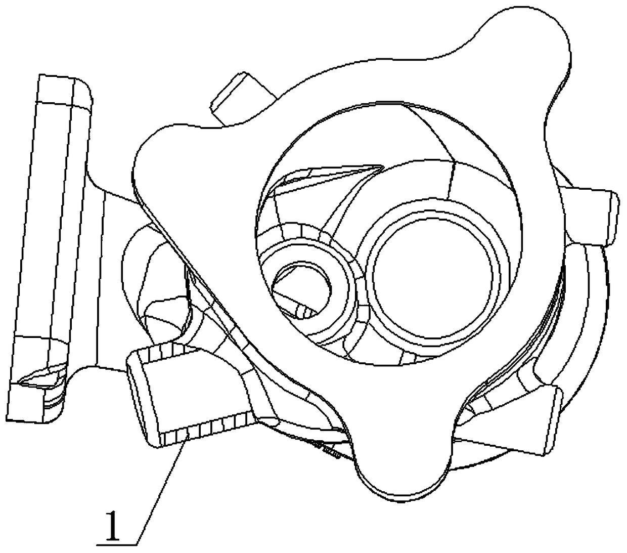
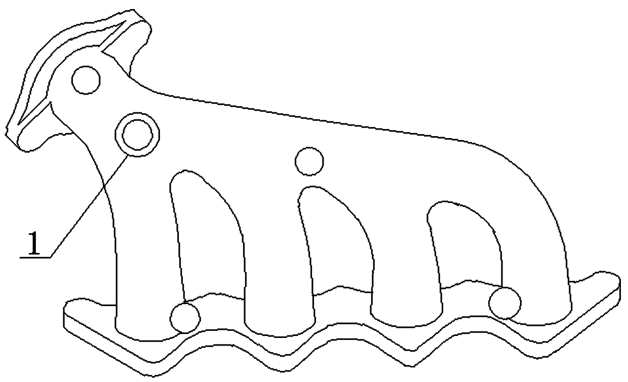
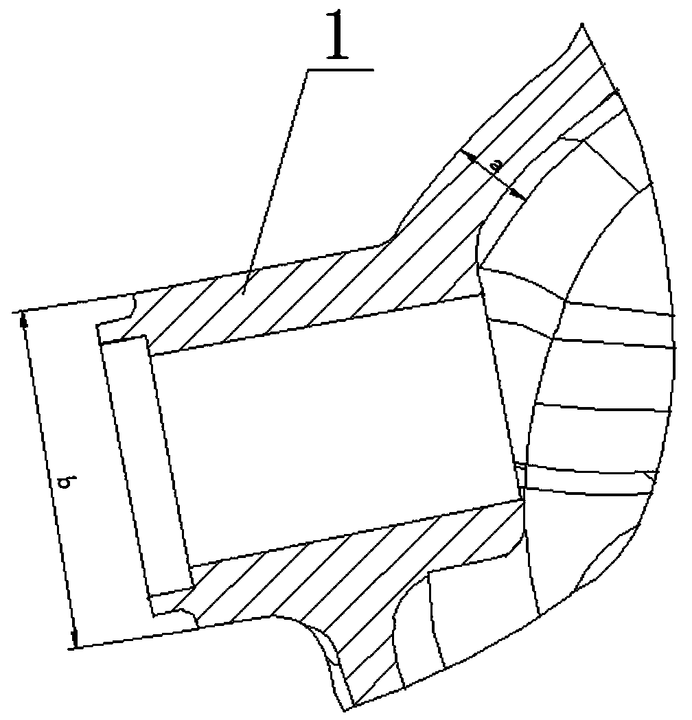
[0035] Such as figure 1 and figure 2 As shown, the diameter of the bolt 1 on the volute and the exhaust pipe casting is 20-30mm, and threaded holes need to be processed on the bolt 1 to facilitate subsequent installation and fixing. The conventional processing method is to fill up the processing hole, cast the blank, and then machine the threaded hole, or use blind hole casting, but from the attached image 3 It can be seen that the thickness a of the pipe wall of the casting is 4-5mm, while the diameter b of the bolt is 26mm, and there is an area where the thickness is connected, thus forming a T-shaped hot node area; when the molten iron is cast, the thickness of the casting is uneven, and the thin-walled part The solidification time is less than that of the thick part, and the heat of the thick part is large, and finally the solidification shrinks, and the bolts have defects such as shrinkage and shrinkage.

[0036] Therefore the present invention discloses a method for ...

Embodiment 2

[0047] The structure of embodiment 2 is basically the same as that of embodiment 1, the difference is:

[0048] The sand core is prepared from the following raw materials in parts by weight: 100 parts of silica raw sand, 1.8 parts of polyethylene resin, 2.2 parts of curing agent and 1.4 parts of calcium stearate.

[0049] Wherein the curing agent is urotropine.

[0050] Sand cores are prepared by the following steps:

[0051] 1) Sand mixing step: mix and stir the above raw materials to form uniform mixed sand;

[0052] 2) Core box design, installation and heating: Design the core box mold according to the drawings, such as Figure 7 As shown, the upper part is the movable mold 5, and the lower part is the static mold 6. After adding the tooling, install it on the core shooter and heat it. The dynamic and static molds are heated to 240 and 220 °C respectively;

[0053] 3) Sand filling step: inject the mixed sand into the dynamic and static mold core boxes respectively throug...

Embodiment 3

[0057] The structure of embodiment 3 is basically the same as that of embodiment 1, the difference is:

[0058] The sand core is prepared from the following raw materials in parts by weight: 100 parts of silica raw sand, 2.0 parts of polyethylene resin, 2.2 parts of curing agent and 1.3 parts of calcium stearate.

[0059] Wherein the curing agent is urotropine.

[0060] Sand cores are prepared by the following steps:

[0061] 1) Sand mixing step: mix and stir the above raw materials to form uniform mixed sand;

[0062] 2) Core box design, installation and heating: Design the core box mold according to the drawings, such as Figure 7 As shown, the upper part is the movable mold 5, and the lower part is the static mold 6. After adding the tooling, install it on the core shooter and heat it. The dynamic and static molds are heated to 240 and 220 °C respectively;

[0063] 3) Sand filling step: inject the mixed sand into the dynamic and static mold core boxes respectively throug...


PUM

PropertyMeasurementUnit
thicknessaaaaaaaaaa
diameteraaaaaaaaaa
compressive strengthaaaaaaaaaa

Abstract

The invention discloses a method for overcoming a casting bolt shrinkage porosity defect and relates to the technical field of casting. The method specially comprises the steps that when a casting sand core is prepared, a hole-forming boss is arranged at the corresponding position of the center of a casting bolt and is in a shape of a circular truncated cone, the hole-forming boss is removed aftera casting is formed through pouring, and a circular truncated cone shaped blind hole is formed in the center of the casting bolt and is machined into a threaded hole. According to the method, the hole-forming boss is arranged at the corresponding position of the center of the casting bolt, a feeding dead head added at the top of the bolt and a quenching chiller added at the bottom are not needed,and the process is simple, low in cost and can overcome the casting bolt shrinkage porosity defect.

Description

technical field [0001] The invention relates to the field of casting technology, in particular to a method for solving the shrinkage defect of casting bolts. Background technique [0002] Such as figure 1 and figure 2 As shown, the bolt diameter of the volute type and exhaust pipe type casting sensor is generally between 20-30mm, and then a threaded hole is processed inside the bolt for installation or fixing. In the previous product design, we filled up the machining holes, cast the blank, and then processed the hole; or used blind hole casting, and then processed the through hole. The disadvantage is that the weight of the blank increases, the cost increases, and the casting The heat section increases, the specific situation is: the bolt diameter of the casting is about 26mm during casting, and the wall thickness of the casting connected with the bolt is 5mm, and there is a thick and thin connected area, thus forming a T-shaped hot section area. When the molten iron is ...

Claims


Application Information

Patent Timeline
Patent Type & Authority Applications(China)
IPC IPC(8): B22C9/22B22C9/10B22C1/00
CPCB22C1/00B22C9/10B22C9/22
Inventor 王瑞金贾建法余嗣瑞李刚王延召闫国福孙稳定
Owner 西峡飞龙特种铸造有限公司
Learn More