Optical fiber drawing tower control system

A control system and wire drawing tower technology, applied in manufacturing tools, glass manufacturing equipment, glass production, etc., can solve the problems of unstable die-piercing success rate and low die-piercing work efficiency, so as to facilitate maintenance and replacement, and save manpower and material resources. , the effect of reducing waste of resources

Pending Publication Date: 2019-03-01
JIANGSU STERLITE TONGGUANG FIBER
View PDF2 Cites 6 Cited by
  • Summary
  • Abstract
  • Description
  • Claims
  • Application Information

AI Technical Summary

Problems solved by technology

[0003] In order to overcome the problems in the prior art that the working efficiency of the drawing tower is low and the success rate of passing the mold is unstable during the optical fiber production process, the present invention provides a control system for an optical fiber drawing tower, including a drawing tower, a prefabricated rod Core adjustment device, heating furnace, bare fiber diameter measuring instrument, waste optical fiber collection device, mold threading device, coating conta

Method used


Image

  • Optical fiber drawing tower control system
  • Optical fiber drawing tower control system
  • Optical fiber drawing tower control system

Examples


Embodiment 1

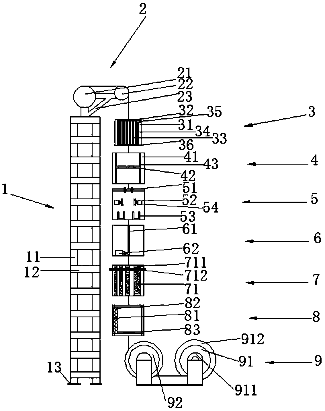
[0031] like figure 1 Shown: a control system for an optical fiber drawing tower, including a drawing tower 1, a preform core adjustment device 2, a heating furnace 3, a bare fiber diameter measuring instrument 4, a waste optical fiber collection device 5, a mold passing device 6, and a coating container 7 , curing furnace 8 and traction device 9; the wire drawing tower 1 is vertically arranged on the ground, the preform core adjustment device 2 is arranged on the top of the wire drawing tower, the heating furnace 3, the bare fiber diameter measuring instrument 4, the waste optical fiber The collecting device 5 , the mold passing device 6 , the coating container 7 , and the curing furnace 8 are sequentially installed on the side of the wire drawing tower 1 from top to bottom, and the traction device 9 is installed on the ground and connected with the curing furnace 8 .

[0032] like figure 1 As shown: the drawing tower 1 consists of four longitudinal steel pipes 11 and several...

Embodiment 2

[0037] like figure 1 Shown: a control system for an optical fiber drawing tower, including a drawing tower 1, a preform core adjustment device 2, a heating furnace 3, a bare fiber diameter measuring instrument 4, a waste optical fiber collection device 5, a mold passing device 6, and a coating container 7 , curing furnace 8 and traction device 9; the wire drawing tower 1 is vertically arranged on the ground, the preform core adjustment device 2 is arranged on the top of the wire drawing tower, the heating furnace 3, the bare fiber diameter measuring instrument 4, the waste optical fiber The collecting device 5 , the mold passing device 6 , the coating container 7 , and the curing furnace 8 are sequentially installed on the side of the wire drawing tower 1 from top to bottom, and the traction device 9 is installed on the ground and connected with the curing furnace 8 .

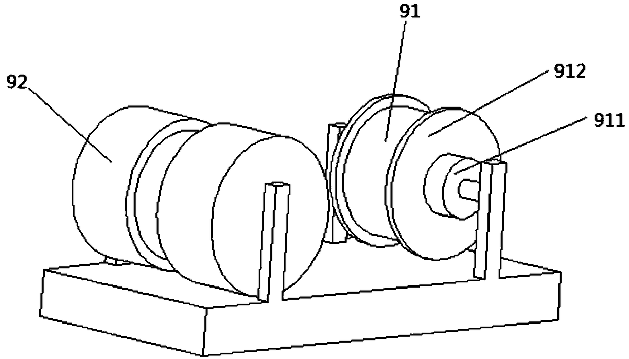
[0038] like figure 1 and Figure 4 As shown: the waste optical fiber collection device 5 is a drum structu...


PUM


Abstract

The invention provides an optical fiber drawing tower control system which comprises a drawing tower frame, a preform core adjusting device, a heating furnace, a bare fiber diameter measuring instrument, a waste optical fiber collecting device, a die passing device, a coating container, a curing furnace and a traction device. The drawing tower frame is vertically arranged on the ground, the preform core adjusting device is arranged at the tower top of the drawing tower frame, the heating furnace, the bare fiber diameter measuring instrument, the waste optical fiber collecting device, the die passing device, the coating container and the curing furnace are sequentially installed on the side face of the drawing tower frame, the traction device is installed on the ground and is connected withthe curing furnace. In the field of optical fiber production line control, the problem of low production efficiency of artificial die passing needed in a drawing tower is solved, the quality of optical fibers and the production efficiency are improved, and the production cost is saved.

Description

technical field [0001] The invention relates to the technical field of optical fiber production line control, in particular to an optical fiber drawing tower control system. Background technique [0002] In the production process of optical fiber, the fiber preform is usually heated, coated, solidified and other processes to obtain the formed optical fiber. The various steps of optical fiber production need to be closely coordinated. The appearance of the optical fiber drawing tower satisfies the For this demand, Chinese patent CN106854036A is used to prepare a drawing tower for diamagnetic optical fiber, including a drawing tower: the upper part of the drawing tower is provided with a rod feeding and aligning device, and the lower part is provided with a traction device, and the rod feeding and aligning device and The traction device is used to transport the diamagnetic optical fiber preform; the graphite heating furnace, laser caliper, coating container and ultraviolet cur...

Claims


Application Information

Patent Timeline
IPC IPC(8): C03B37/025C03B37/16C03C25/104C03C25/12
CPCC03B37/025C03B37/16C03C25/104C03C25/12Y02P40/57
Inventor 严万华孙建彬裴丽维捷杨梅
Owner JIANGSU STERLITE TONGGUANG FIBER
Why Eureka
Try Eureka