
Sludge and kitchen waste co-digestion system and operation method thereof

A food waste and digestion system technology, applied in biochemical equipment and methods, biological sludge treatment, biochemical instruments, etc., can solve the problems of acidic pH value of the system, low methane production efficiency, and easy accumulation of large quantities, etc., to achieve system Improved stability, improved removal rate, and reduced pathogenic bacteria

Pending Publication Date: 2019-03-01
SHANGHAI MUNICIPAL ENG DESIGN INST GRP
View PDF4 Cites 1 Cited by
  • Summary
  • Abstract
  • Description
  • Claims
  • Application Information

AI Technical Summary

Problems solved by technology

Sludge and kitchen waste single-phase co-digestion system, although the device is simple, but it is easy to accumulate a large amount of SCFAs in the acid production stage, making the pH of the system acidic, resulting in the inhibition of the methane production process, and eventually causing the system to collapse
The sludge and kitchen waste two-phase co-digestion system puts the hydrolysis acid production stage and the methane production stage in two reactors respectively, so that the microorganisms in different stages can live in the best living environment, and avoid the excessive accumulation of SCFAs on the methane production process. However, existing studies have shown that the solid residence time (SRT) of this system still needs to be 25d or longer, and the methane production efficiency is also low

Method used


Image

  • Sludge and kitchen waste co-digestion system and operation method thereof

Examples


Embodiment Construction

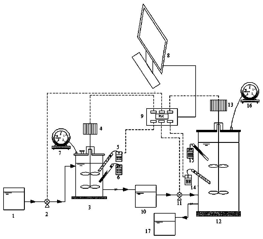
[0032] The patent application is further described in conjunction with accompanying drawings and examples: as figure 1 As shown, the device of the present invention includes a mixture storage tank, a high-temperature fermentation tank, a cooling adjustment tank, a medium-temperature methanogenic reactor, and a digestion mixture storage tank. Among them, the high-temperature fermentation tank and the medium-temperature methanogenic reactor are made of plexiglass; the mixture storage tank, the cooling adjustment tank, and the digestion mixture storage tank are made of organic plastic.

[0033] The mixture storage tank 1 of the device of the present invention is connected with the high-temperature fermentation tank 3 through the first peristaltic pump 2, and the high-temperature fermentation tank 3 is equipped with a first stirrer 4, a first temperature controller 5, a first pH monitor 6 and a first gas flow meter 7. The high-temperature fermenter 3 is connected to the cooling ad...


PUM

PropertyMeasurementUnit
particle diameteraaaaaaaaaa

Abstract

The invention discloses a sludge and kitchen waste co-digestion system. A mixture storage tank is connected with a high-temperature fermentation tank through a first peristaltic pump; the high-temperature fermentation tank is connected with a cooling adjusting tank; the cooling adjusting tank is connected with a middle-temperature methane-producing reactor through a second peristaltic pump; the middle-temperature methane-producing reactor is connected with a digested mixture storage tank. According to the sludge and kitchen waste co-digestion system, sludge is uniformly mixed with kitchen waste at first; then an obtained mixture is pumped into the high-temperature fermentation tank to be subjected to hydrolytic acidification; finally, a sludge and kitchen waste fermentation mixture is pumped into the middle-temperature methane-producing reactor to produce methane. According to the method, a hydrolytic acid production phase and a methane production phase of a co-digestion process are carried out in two reactors; high temperature is controlled at the hydrolytic acid production phase and middle temperature is controlled at the methane production phase. The hydrolytic acid production efficiency is improved; meanwhile, an optimal living environment is provided for hydrolytic acid production bacteria and methane production bacteria; the inhibition, caused by the fact that sludge andkitchen waste single-phase co-digestion short-chain fatty acid (SCFAs) is excessively accumulated, on a methane production process is avoided.

Description

technical field [0001] The invention discloses a sludge and kitchen waste co-digestion system and an operation method thereof, which can start quickly, run stably and improve methane production efficiency, and belong to the field of solid waste resource utilization. Background technique [0002] Sludge and food waste are the main components of municipal solid waste. With the continuous expansion of sewage treatment plants in my country, the increase of sewage treatment capacity and the development of cities, the output of sludge and kitchen waste is also increasing. The current treatment and disposal methods for sludge and kitchen waste mainly include landfill, incineration, composting and anaerobic digestion. Among the many treatment and disposal methods, anaerobic digestion technology is widely used because it can recover biogas energy while degrading food waste and sludge. Municipal sludge in my country has the characteristics of high sand content, low C / N, low organic ...

Claims


Application Information

Patent Timeline
Patent Type & Authority Applications(China)
IPC IPC(8): C12M1/38C12M1/36C12M1/02C12M1/107C12M1/00C02F11/04
CPCC12M21/04C12M27/02C12M41/12C12M41/26C12M41/34C02F11/04Y02E50/30
Inventor 袁悦张辰谭学军王磊
Owner SHANGHAI MUNICIPAL ENG DESIGN INST GRP
Learn More