Method and device for demodulating distributed optical fiber vibration sensing system

A vibration sensing system, distributed optical fiber technology, applied in measurement devices, instruments, measurement of ultrasonic/sonic/infrasonic waves, etc., can solve the effects of changes in polarization state of light source and frequency stability of demodulation accuracy, high complexity, and high response. Slow speed and other problems, to achieve the effect of easy implementation, high flexibility, and reduced response time

Pending Publication Date: 2019-03-01
珠海任驰光电科技有限公司
View PDF4 Cites 15 Cited by
  • Summary
  • Abstract
  • Description
  • Claims
  • Application Information

AI Technical Summary

Problems solved by technology

Demodulation accuracy is easily affected by polarization state changes and frequency stability of the light source
The demodulation process includes operations such as frequency mixing, filtering, and difference, with high complexity and slow response speed

Method used


Image

  • Method and device for demodulating distributed optical fiber vibration sensing system
  • Method and device for demodulating distributed optical fiber vibration sensing system
  • Method and device for demodulating distributed optical fiber vibration sensing system

Examples


Embodiment 1

[0028] In one or more embodiments, a demodulation method for a distributed optical fiber vibration sensing system is disclosed, including: two continuous ultra-narrow linewidth lasers with the same optical power are respectively subjected to acousto-optic modulation and electro-optic modulation to obtain two pulses Light; input the pulse width of the two pulsed lights to the sensing fiber 11; the backward Rayleigh scattered light of the two pulsed optical signals will produce the set frequency difference, so that the return Rayleigh optical signal presents sine wave interference fringes When the disturbance signal acts on the sensing fiber 11, the phase difference of the returned Rayleigh optical signal changes, and the vibration waveform and position sensed by the sensing fiber 11 are obtained according to the phase difference.

[0029] The ultra-narrow linewidth laser source is divided into two continuous beams of the same power, which pass through the acousto-optic modulator 5 ...

Embodiment 2

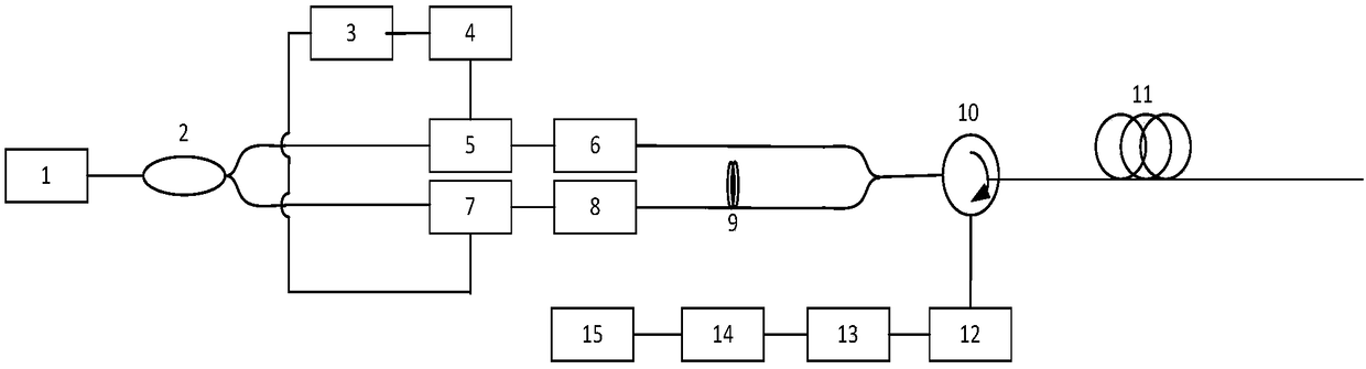
[0046] In one or more embodiments, a demodulation device for a distributed optical fiber vibration sensing system is disclosed, such as figure 1 As shown, it includes: the light source module 1 is connected with the coupler 2, and the output of the coupler 2 is divided into two paths, one of which is connected in series with the acousto-optic modulator 5 and the first erbium-doped fiber amplifier 6 (EDFA), and then passes through the first optical fiber Connected to the circulator 10; the other is connected in series with the electro-optical modulator 7 and the second erbium-doped fiber amplifier 8 (EDFA), and then connected to the circulator 10 through the second optical fiber 9; the circulator 10 is connected to the sensing fiber 11; The circulator 10 connects the photoelectric conversion module 12, the high-pass filter 13, the data acquisition module 14 and the host computer 15 in series in sequence.

[0047] The first optical fiber and the second optical fiber 9 are separated ...

Embodiment 3

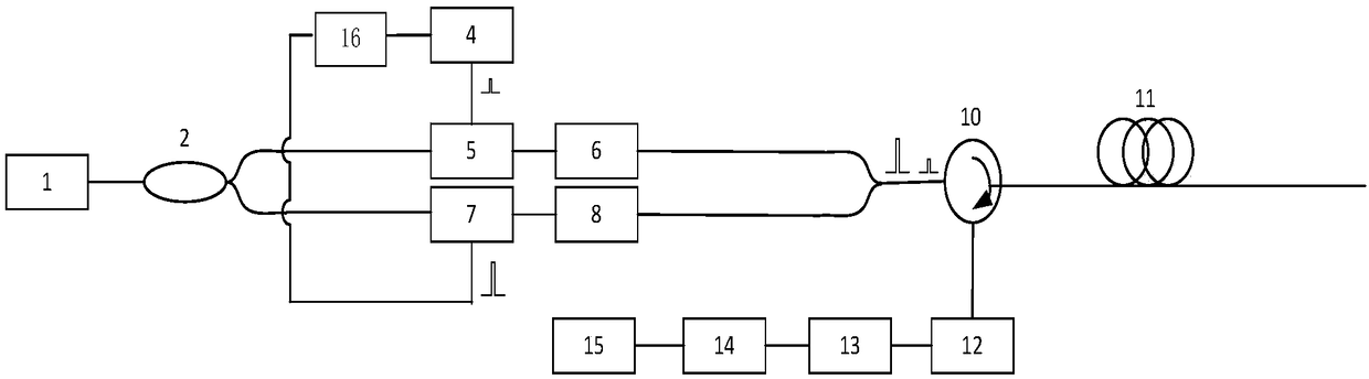
[0056] The demodulation device of a distributed optical fiber vibration sensing system disclosed in this embodiment, such as figure 2 As shown, unlike the device in the second embodiment, in this embodiment, the transmission length of the first optical fiber and the second optical fiber 9 are the same, and the double pulse signal generator 16 is used to drive the acousto-optic modulator 5 and the electro-optic modulator 7 The optical pulses are modulated separately, and the modulation interval is one modulation pulse width to enter the two optical paths, replacing the optical path difference of the two optical fibers, and reducing the impact of environmental factors.

[0057] The rest of the structure and working process are the same as those in the second embodiment, and will not be repeated.


PUM


Abstract

The invention discloses a method and device for demodulating a distributed optical fiber vibration sensing system. The method comprises that two continuous ultra-narrow linewidth lasers with the sameoptical power are subjected to acousto-optic modulation and electro-optic modulation to be converted into two pulsed light signals; the two pulsed light signals are input into a sensing fiber at an interval of set pulse width; the backward Rayleigh scattered light of the two pulsed light signals generate a set frequency difference such that the returned Rayleigh light signals exhibit sinusoidal interference fringes; when a disturbance signal has an effect on the sensing fiber, the phase difference of the returned Rayleigh light signals changes, and the vibration waveform and position sensed bythe sensing fiber are obtained according to the phase difference. When the disturbance signal appears, a detector can quickly obtain the position of the disturbance signal and the intensity of the disturbance signal, which solves the problem that the demodulation algorithm of a [phi]-OTDR system is complex and a laser frequency drifts, and guarantees that the positioning error of the system is within +/-1m.

Description

Technical field [0001] The invention relates to the technical field of optical fiber sensing, in particular to a demodulation method and device for a distributed optical fiber vibration sensing system. Background technique [0002] Distributed optical fiber vibration sensing system can realize long-distance, distributed disturbance sensing and signal transmission. By detecting the light intensity changes of the backscattered interference light of various parts of the optical fiber, it can realize the detection of external intrusive activities, combined with optical time domain reflection technology It can realize the accurate positioning of the vibration signal. The distributed optical fiber vibration sensing system uses the optical fiber itself as the carrier of sensor and signal transmission. It has the advantages of high measurement accuracy, fast response speed, and intrinsic safety. It can be used in flammable, explosive, high temperature, high humidity, high corrosion and s...

Claims


Application Information

Patent Timeline
Patent Type & Authority Applications(China)
IPC IPC(8): G01H9/00
CPCG01H9/004
Inventor 崔洪亮付群健于淼罗政纯
Owner 珠海任驰光电科技有限公司
Why Eureka
Try Eureka