
Non-removing rotor dynamic balancing method

A rotor dynamic balancing and rotor technology, which is applied in the field of rotor dynamic balancing, can solve the problems of too many machines and equipment, improper gas cutting operation, and low balancing accuracy, and achieve the effects of improving balancing efficiency, reducing balancing cost, and improving balancing accuracy.

Active Publication Date: 2019-12-06
ZHEJIANG UNIV
View PDF13 Cites 0 Cited by
  • Summary
  • Abstract
  • Description
  • Claims
  • Application Information

AI Technical Summary

Problems solved by technology

[0005] 1. When the rotor rotates at high speed, the test weight will bear a large centrifugal force. In order to prevent the rotor from being thrown out during the rotation and causing a safety accident, it is required to weld the test weight as firmly as possible. However, because the test weight is If it needs to be removed, the test weight is welded too firmly and it is very troublesome to remove it. How to weld as little as possible while ensuring safety has always troubled the dynamic balance operator
[0006] 2. Only welding torch, welding rod and welding machine are needed for weight reduction. Flame gas cutting is generally used for weight removal. The process is more complicated and requires cutting gun. Oxygen and acetylene are both explosive gases, which pose a safety hazard.
Therefore, the dynamic balancing method that not only adds weight but also removes weight requires a lot of machinery and equipment, and has high technical requirements for workers. The labor intensity in the balancing process is high, the balancing time is long, and the efficiency is low. In practice, it is often impossible to perform dynamic balancing due to lack of oxygen or acetylene. balance
[0007] When de-weighting, too much or too little weight may be subtracted, resulting in a decrease in the final balance accuracy. In addition, improper gas cutting operation may easily cause serious deformation of the rotor due to local overheating and damage the balance of the rotor.

Method used


Image

  • Non-removing rotor dynamic balancing method
  • Non-removing rotor dynamic balancing method
  • Non-removing rotor dynamic balancing method

Examples


Embodiment Construction

[0033] The present invention will be further described below in conjunction with drawings and embodiments.

[0034] A method for dynamic balancing without weight removal, comprising the steps of:

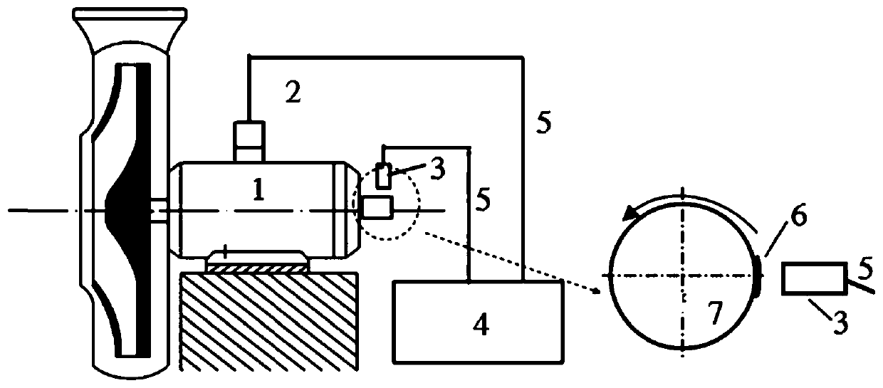
[0035] Step 1: Install the vibration sensor 2 in the horizontal direction of the rotor bearing seat 1 to pick up the vibration signal x(t); paste a reflective paper 6 on the rotor shaft 7, and put the speed sensor 3 against the reflective paper 6 to pick up the rotor The speed signal s(t), the vibration sensor 2 and the speed sensor 3 are respectively connected with the dynamic balancer 4 with the cable 5, the vibration signal and the rotor speed signal are transmitted to the dynamic balancer 4, and the rotor is measured by the dynamic balancer Amplitude and phase of unbalanced vibrations. The installation position relationship of each part is as follows: figure 1 shown.

[0036] Step 2: Start the rotor and measure the amplitude A of the original unbalanced vibration signal of th...


PUM


Abstract

The invention discloses a rotor dynamic balancing method without weight removal, and belongs to the technical field of rotor dynamic balance. The rotor dynamic balancing method without weight removalprovided by the invention can achieve balance just by adding weights twice, eliminates a weight removal process, greatly improves balance precision, reduces balance cost, improves balance efficiency,and avoids accidents. The method comprises steps of a, installing a vibration sensor horizontally on a rotor bearing seat to acquire a vibration signal, attaching reflective paper to a rotor shaft, measuring a rotational speed signal by using a speed sensor facing the reflective paper, and measuring the amplitude and the phase of the unbalanced vibration of the rotor by a dynamic balancer; b, after a test weight is added, measuring the amplitude and the phase of the unbalanced vibration again; and c, solving the magnitude and the position of the unbalanced weight according to a formula, addingthe same correcting weight to an opposite side so as to greatly reduce the vibration and achieve balance.

Description

technical field [0001] The invention belongs to the technical field of rotor dynamic balance, and in particular relates to a method for dynamic balance of a non-weight-removing rotor. Background technique [0002] Rotating machinery is a mechanical equipment with rotor as the main component, which is widely used in petrochemical, aerospace, shipbuilding, automobile, water conservancy and other fields. Due to manufacturing, installation errors and wear during operation, the rotor will inevitably have an unbalanced mass distribution. The unbalance of the rotor is the main excitation source of rotating machinery, and it is also the trigger factor of many self-excited vibrations. Unbalance will cause disturbance and internal stress of the rotor, cause vibration and noise of the machine, accelerate the wear of bearings and shaft seals, and reduce the working efficiency of the machine. In order to reduce vibration and prolong the service life of the machine, the rotor must be ba...

Claims


Application Information

Patent Timeline
Patent Type & Authority Patents(China)
IPC IPC(8): G01M1/32
CPCG01M1/32
Inventor 张志新王春鹏
Owner ZHEJIANG UNIV
Learn More