Preparation method of carbon fiber composite reflector and related reflector

A technology of composite materials and mirrors, which is applied in the direction of mirrors, etc., can solve the problems of large longitudinal deformation of the mirror, difficulty in ensuring the close fit of the honeycomb and the panel, and poor thermal stability of the mirror.

Active Publication Date: 2021-08-20
CHANGCHUN INST OF OPTICS FINE MECHANICS & PHYSICS CHINESE ACAD OF SCI
View PDF5 Cites 0 Cited by
  • Summary
  • Abstract
  • Description
  • Claims
  • Application Information

AI Technical Summary

Problems solved by technology

[0006] 1. The reflector is a fully enclosed structure, and the load-carrying efficiency is not as high as that of the semi-closed structure
[0007] 2. The thermal expansion coefficient of the honeycomb material is inconsistent with that of the panel material, resulting in poor thermal stability of the reflector
[0008] 3. The load-bearing characteristics of the honeycomb have obvious directionality, the bending resistance and compression resistance are relatively good, and the shear resistance is relatively poor, resulting in relatively large longitudinal deformation of the mirror and poor overall dimensional stability.
[0009] 4. Difficulty in forming curved surfaces
For flat mirrors, it is easier to connect the honeycomb to the upper and lower panels, but for curved mirrors, it is difficult to ensure the close fit of the honeycomb and the panel
If the bonding between the honeycomb and the panel is not good, it will affect the bonding uniformity and bonding strength between the honeycomb and the panel

Method used


Image

  • Preparation method of carbon fiber composite reflector and related reflector
  • Preparation method of carbon fiber composite reflector and related reflector
  • Preparation method of carbon fiber composite reflector and related reflector

Examples


preparation example Construction

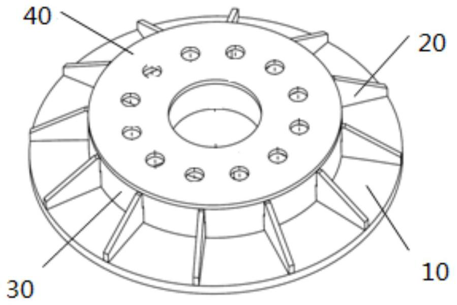
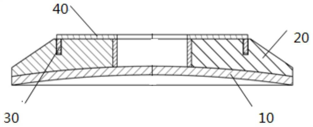
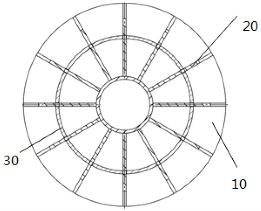
[0038] The invention provides a method for preparing a carbon fiber composite mirror, comprising:

[0039] Step 1, preparing the reflector panel 10: laying carbon fiber composite material prepreg on the mold of the reflector panel 10, and vacuum curing and forming;

[0040] Step 2. Prepare radial ribs 20 of the reflector: spread the carbon fiber composite material prepreg on the plane mold, and vacuum solidify to obtain a carbon fiber composite material flat plate, and process the carbon fiber composite material flat plate by cutting to obtain a shape matching the reflector panel. Mirror radial ribs 20;

[0041] Step 3. Preparing the reinforcing rib 30 in the circumferential direction of the reflector: laying the carbon fiber material prepreg on the cylinder mold, curing in a vacuum to obtain a cylinder of carbon fiber composite material, and processing the cylinder by cutting to obtain the reinforcing rib 30 in the circumferential direction of the reflector;

[0042] Step 4,...

Embodiment 1

[0059] The preparation steps of the carbon fiber composite mirror in the present invention are as follows:

[0060] In the first step, the mirror panel 10 is prepared. The high-modulus carbon fiber composite material prepreg is applied to the high-precision mold, and the lay-up adopts quasi-isotropic lay-up. Then put it into a vacuum bag and put it into a vacuum tank to solidify and form. According to different resin types, the range of curing temperature is 120-180°C, and the range of curing pressure is 0.1-1.0Mpa.

[0061] In this embodiment, M40JB is selected as the carbon fiber composite material, and the Young's modulus of the carbon fiber along the fiber direction is about 384Gpa; while for ordinary T700 carbon fiber composite material, the Young's modulus of the carbon fiber along the fiber direction is about 235Gpa.

[0062] The selection of curing parameters is affected by various factors. In this embodiment, the high temperature curing epoxy resin has a curing temp...


PUM


Abstract

The invention provides a method for preparing a carbon fiber composite material reflector and a carbon fiber composite material reflector, comprising the steps of preparing a reflector panel, a reflector radial reinforcement rib, a reflector circumferential direction reinforcement rib and a reflector back plate, and The step of assembling the reflector panel, the reflector radial reinforcement rib, the reflector circumferential direction reinforcement rib and the reflector back plate into a carbon fiber composite reflector. The preparation method of the carbon fiber composite reflector and the carbon fiber composite reflector provided by the present invention can realize the high light weight rate of the reflector and the low-cost manufacture of small batches on the premise of ensuring the surface shape accuracy of the reflector.

Description

technical field [0001] The invention relates to the technical field of optical element structures, in particular to a method for preparing a carbon fiber composite mirror and the carbon fiber composite mirror. Background technique [0002] With the advancement of optical imaging technology, optical imaging systems are developing towards large aperture, high resolution, high mobility and high automation. However, increasing the aperture of the optical system and improving the resolution of the optical system will cause an increase in the weight and volume of the mirror, and at the same time, the weight of the supporting structure that matches it will increase more significantly. This will have a great impact on the flexibility of the optical imaging system, especially for space optical equipment, the weight of the optical system will directly affect the launch cost. The light weight of optical mirror is a key point to realize the light weight of optical system. [0003] Lig...

Claims


Application Information

Patent Timeline
Patent Type & Authority Patents(China)
IPC IPC(8): G02B5/08G02B5/10
CPCG02B5/08G02B5/10
Inventor 谢军刘震宇程路超何锋赟余毅
Owner CHANGCHUN INST OF OPTICS FINE MECHANICS & PHYSICS CHINESE ACAD OF SCI
Why Eureka
Try Eureka