
Thermoelectric device and method of manufacturing the same

a technology of thermoelectric devices and manufacturing methods, applied in the direction of thermoelectric device manufacturing/treatment, thermoelectric device with peltier/seeback effect, etc., can solve the problems of increasing processing costs, difficult to realize large-area production, and high cost of semiconductor metal materials or ceramic materials, and achieves easy maintenance of large temperature differences, high flexibility and light weight. , the effect of facilitating large-area production

Inactive Publication Date: 2018-09-13
CENT FOR ADVANCED SOFT ELECTRONICS +1
View PDF3 Cites 0 Cited by
  • Summary
  • Abstract
  • Description
  • Claims
  • Application Information

AI Technical Summary

Benefits of technology

The present invention provides a thermoelectric device with a zigzag configuration, which allows for the use of a thin thermoelectric material and a vertical temperature difference, resulting in a highly flexible and lightweight device. The thickness of the device can be adjusted regardless of the thickness of the film used, making it easy to maintain a large temperature difference without the need for a heat sink. The manufacturing method is cost-effective for large-area production.

Problems solved by technology

Such materials have excellent thermoelectric properties but mostly have high density and thus are disadvantageous in that they are heavy when used in large amounts in order to produce high power.
Furthermore, almost all semiconductor metal materials or ceramic materials are expensive, and the processing thereof includes high-temperature and high-pressure processes, thus increasing processing costs, making it difficult to realize large-area production.
Hence, there are limits to the extent to which the weight of such thermoelectric devices using the corresponding materials can be reduced and to which the shape thereof can be changed, and breakdown may occur upon vibration or impact due to the high brittleness thereof, which is undesirable.

Method used


Image

  • Thermoelectric device and method of manufacturing the same
  • Thermoelectric device and method of manufacturing the same
  • Thermoelectric device and method of manufacturing the same

Examples


example 1

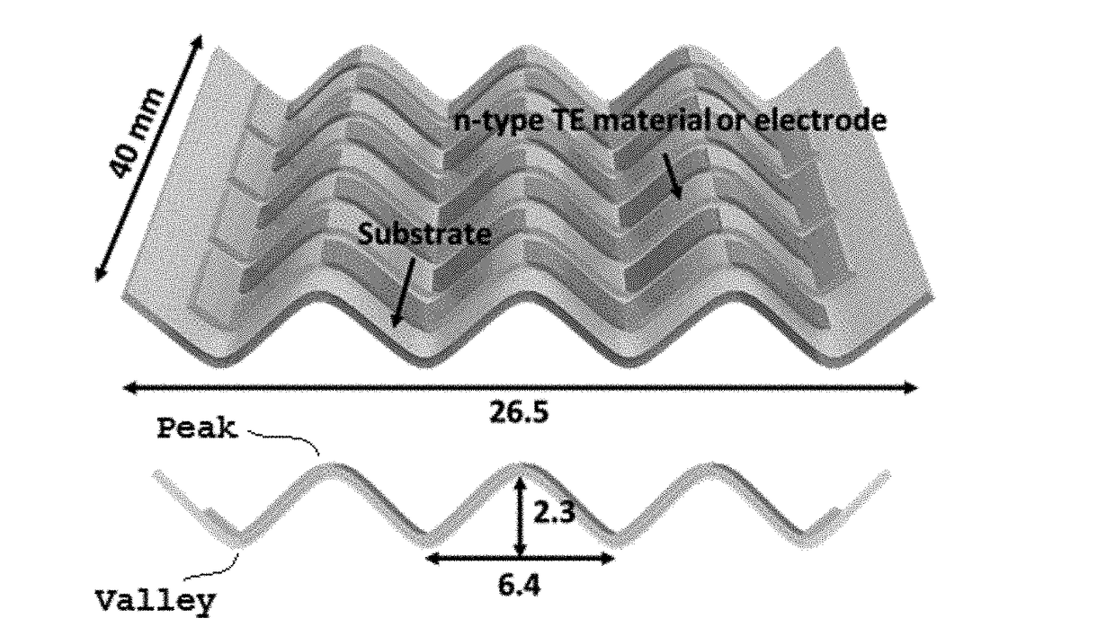
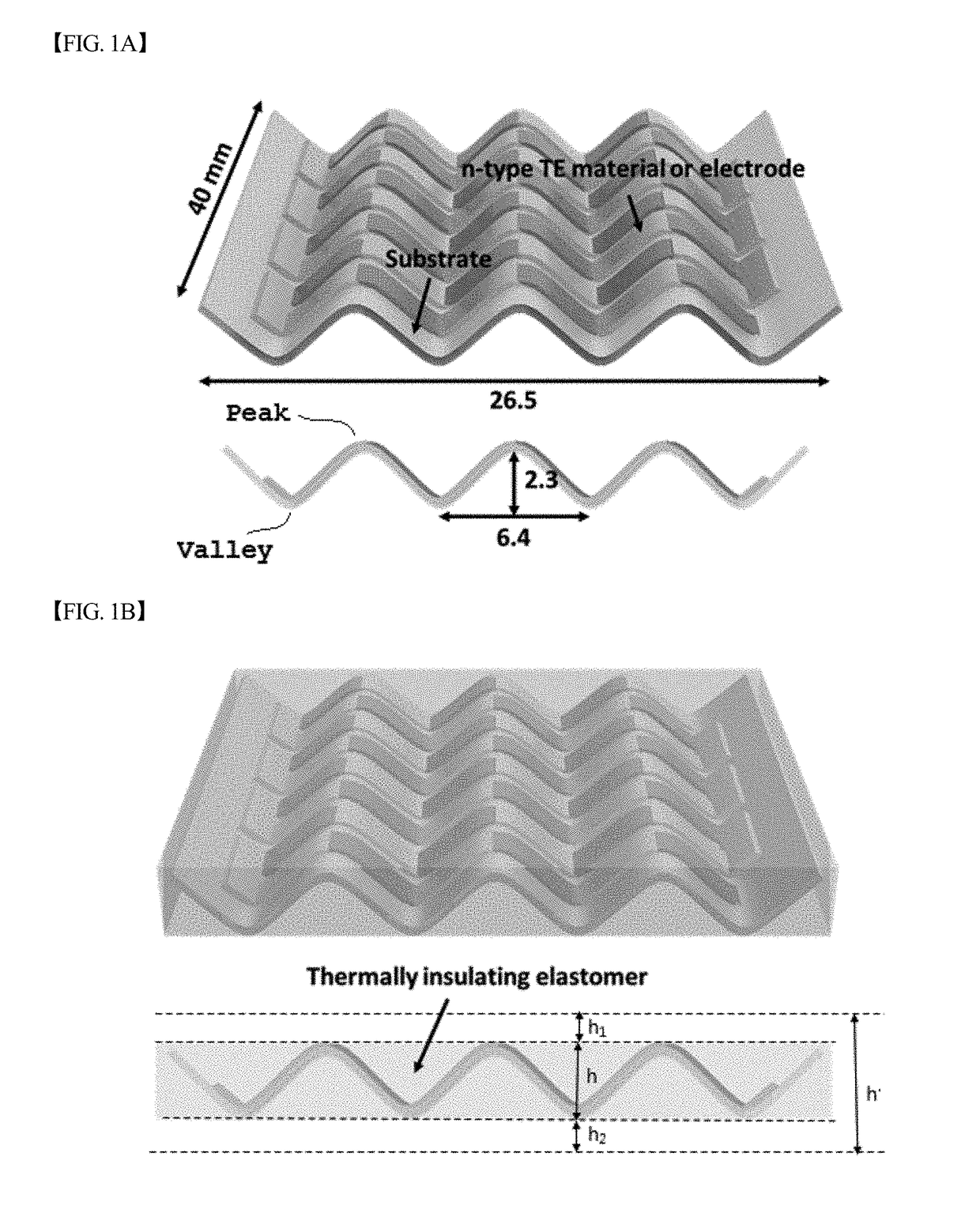
[0058]A PET flexible substrate having a width of 40 mm and a length of 40 mm was patterned so that PEDOT:PSS, serving as a p-type thermoelectric material, and titanium (Ti) 10 nm / gold (Au) 60 nm, serving as an electrode material, were alternately continuously disposed thereon to form 24 PEDOT:PSS patterns. Before the PEDOT:PSS patterning, the wettability of the surface of PET was improved through RIE treatment (250 W, O2 100 sccm, 2 min), and the PEDOT:PSS patterns were obtained by coating a shadow mask-covered PET flexible substrate with a PEDOT:PSS thin film having a thickness of less than 100 nm using a gas spray and then increasing the thickness thereof to about 2 to 3 μm through electrospraying. Thereafter, annealing at 150° C. for 20 min and then dipping in ethylene glycol for 1 hr were conducted, and the device taken out of the ethylene glycol was washed with ethanol and blown using nitrogen (N2) gas. Next, the patterned flexible substrate was placed between pressing plates a...

example 2

[0059]The top and bottom of the thermoelectric device of Example 1 were fixed with silicone grease-coated glass, after which polyurethane and a foaming agent in solution phase were mixed at a ratio of 11:10 and then poured into the thermoelectric device. The reaction was carried out at room temperature for one day or longer, thus forming polyurethane foam, from which the glass was then removed, thereby manufacturing a thermoelectric device filled with the polyurethane foam, which is illustrated in FIG. 1B.


PUM

PropertyMeasurementUnit
temperatureaaaaaaaaaa

Abstract

Disclosed is a thermoelectric device, including a flexible substrate having a zigzag configuration in which a vertical cross-section in a longitudinal direction of one surface thereof includes peaks and valleys and a thermoelectric material line positioned on the flexible substrate and configured to include a p-type thermoelectric material and any one of an n-type thermoelectric material and an electrode material, which are alternately continuously disposed, wherein any one of the n-type thermoelectric material and the electrode material is in contact with the p-type thermoelectric material at the peaks and the valleys. The thermoelectric device, having a zigzag configuration, is highly flexible and lightweight, and a thermoelectric material in film form can be utilized to realize a vertical temperature difference, and thus the thickness of the device can be freely adjusted regardless of the film thickness, thereby easily maintaining a large temperature difference even without a heat sink.

Description

CROSS-REFERENCE TO RELATED APPLICATION[0001]This application claims the priority of the Korean Patent Application NO 10-2017-0030748 filed on Mar. 10, 2017, in the Korean Intellectual Property Office, the disclosure of which is incorporated herein by reference.BACKGROUND OF THE INVENTION1. Technical Field[0002]The present invention relates to a thermoelectric device and a method of manufacturing the same, and more particularly to a thermoelectric device having a zigzag configuration including peaks and valleys and a method of manufacturing the same.2. Description of the Related Art[0003]Thermoelectric conversion indicates energy conversion between thermal energy and electrical energy. Thermoelectric conversion is represented by a Peltier effect in which, when current is allowed to flow to a thermoelectric material, a temperature difference is formed between the opposite ends thereof, and conversely by a Seebeck effect, in which electricity is generated when there is a temperature di...

Claims


Application Information

Patent Timeline
Patent Type & Authority Applications(United States)
IPC IPC(8): H01L35/30H01L35/34H10N10/13H10N10/85H10N19/00H10N10/01H10N10/17H10N10/80H10N10/852H10N10/853H10N10/856
CPCH01L35/30H01L35/34H01L35/16H01L35/18H01L35/24H10N19/101H10N10/01H10N10/17H10N19/00H10N10/852H10N10/853H10N10/856H10N10/13H10N10/85H10N10/80
Inventor CHO, KIL WONKIM, DAE GUNJU, DUCK HYUN
Owner CENT FOR ADVANCED SOFT ELECTRONICS
Learn More