
Soldering tin alloy for electronic part bonding electrodes and soldering method

A technology for electronic parts and electrodes, applied in the field of solder alloys and soldering, can solve the problems of poor tensile properties and thermal fatigue properties, coarse structure, cracks, etc., to improve mechanical strength and thermal fatigue properties. , to achieve the effect of the organization

Inactive Publication Date: 2002-11-13
PANASONIC CORP
View PDF4 Cites 2 Cited by
  • Summary
  • Abstract
  • Description
  • Claims
  • Application Information

AI Technical Summary

Problems solved by technology

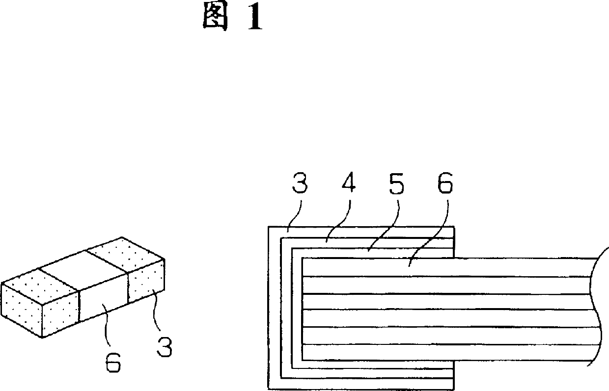
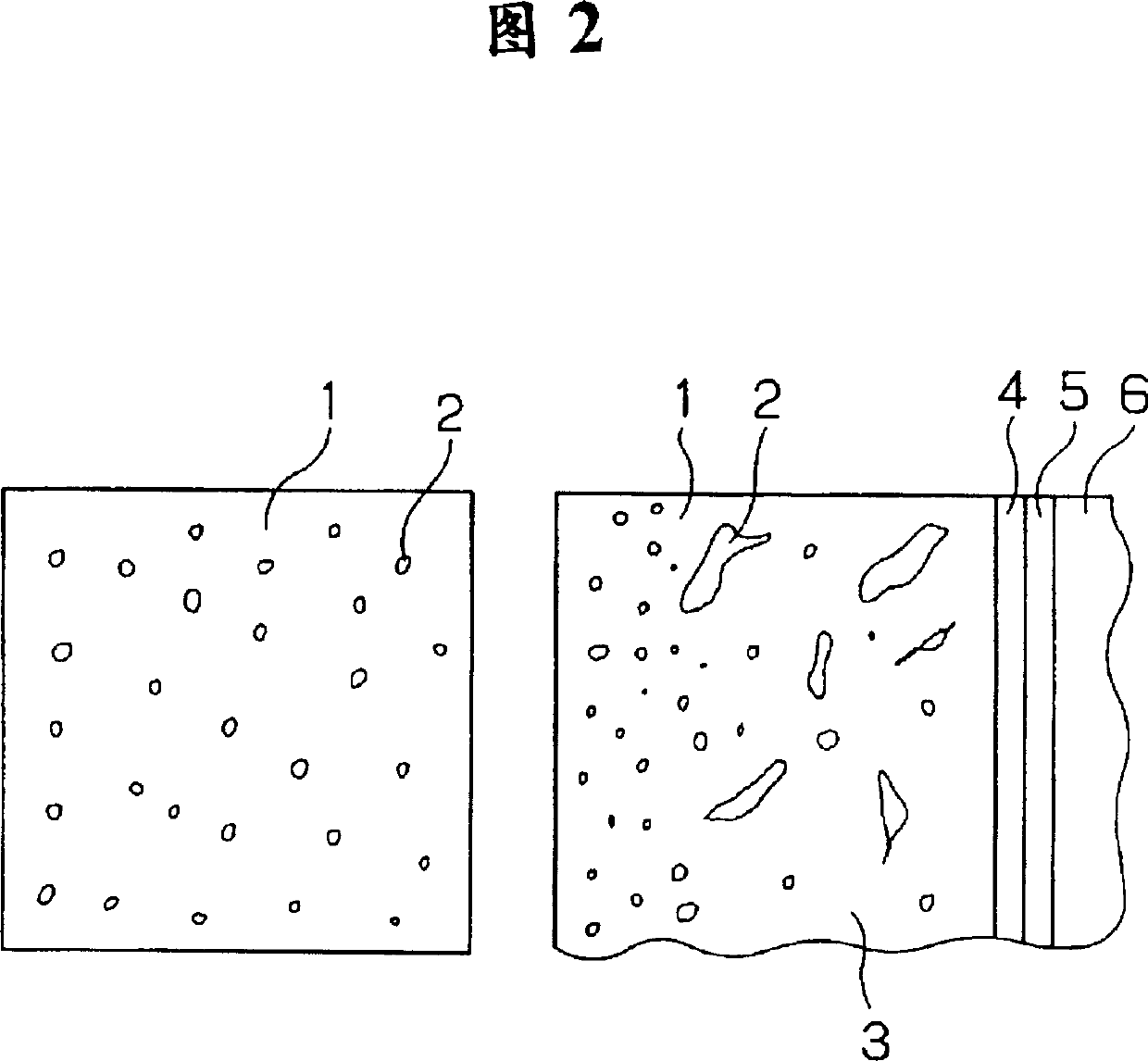
[0005] In the existing soldering, the solder alloy of the joint electrode for soldering of electronic parts has the following problems: when soldering with the solder alloy for joining, the alloy structure is layered, especially when it is repeatedly exposed to high temperature The structure is coarsened in the environment, so when stress is applied to the solder, sliding will occur on the interface of the structure, and cracks will occur as a result.
However, this solder has the problem of poor tensile properties and thermal fatigue resistance.

Method used


Image

  • Soldering tin alloy for electronic part bonding electrodes and soldering method
  • Soldering tin alloy for electronic part bonding electrodes and soldering method
  • Soldering tin alloy for electronic part bonding electrodes and soldering method

Examples


Embodiment 1

[0034] The solder alloy of Example 1 is a three-component solder alloy of Sn 94.5% by weight, Ag 5.0% by weight, and Cu 0.5% by weight.

[0035] The solder alloy was prepared into a paste solder with RMA flux for atmospheric air, and then the melting point, wettability, joint strength, thermal shock and other tests were carried out. The results are shown in Table 1. Although not described in Table 1, the The result of the tensile strength test of this solder was 8.3kgf / mm 2 , the same test result as Comparative Example 2 6.5kgf / mm 2 In contrast, the tensile strength is significantly improved.

[0036] In addition, during the solidification process during soldering, rapid cooling and solidification of the solder can suppress intermetallic compounds (Ag 3 The growth of Sn) makes it into a fine and dispersed state, which is expected to improve its mechanical strength and improve thermal fatigue properties. The above-mentioned α solid solution and β solid solution can also achie...

Embodiment 2

[0038] The solder alloy of Example 2 is a five-component solder alloy of Sn 89.5% by weight, Ag 3% by weight, Bi 5% by weight, Cu 1.5% by weight, and In 1% by weight.

[0039] The results of each test are shown in Table 1, which clearly shows that, compared with Example 1, it can achieve a lowering of the melting point and an increase in the bonding strength.

[0040] The solder alloy of Example 2 was also subjected to rapid cooling and solidification of the solder at the time of soldering. As a result, the mechanical strength was improved and the thermal fatigue resistance was improved as in Example 1.

[0041] As the means of rapid cooling and solidification, as described in Example 1, the method of blowing cold air is preferable, and the cooling rate is 5-15°C / sec, especially about 10°C / sec.

[0042] Ag is solidified by quenching 3 Sn, Cu 3 Sn and Cu 6 Sn 5The resulting metal oxides are refined and dispersed, which can improve mechanical strength and thermal fatigue res...


PUM

PropertyMeasurementUnit
melting pointaaaaaaaaaa

Abstract

To provide a lead-free, fine-structured, and excellent heat-fatigue-resistant solder alloy for electrodes for joining electronic parts. It is a solder alloy for electrodes for joining electronic parts whose main components are Sn, Ag, and Cu. It is characterized in that each component The weight ratio of Sn is 92-97%, Ag 3.0-6.0%, Cu 0.1-2.0%. In the solder with Sn as the main component, by adding a small amount of Ag, the fine alloy structure can be maintained, and the structure change is small, so that an alloy with excellent thermal fatigue resistance can be obtained, and by adding a small amount of Cu, an intermetallic structure can be formed. compound to improve joint strength.

Description

[Technical field] [0001] The present invention relates to a solder alloy on the surface of an electrode for bonding electronic components for component mounting on a circuit board, and a soldering method thereof. [Background technique] [0002] In recent years, in electronic component mounting technology, products using circuit boards on which electrical components are mounted have been increasing, and along with this, there has been a need to improve the mechanical bonding strength of the soldered portion and improve the high reliability such as thermal shock strength. Requirements are getting higher and higher. In addition, amid growing concern for global environmental protection, laws and regulations regarding the disposal of industrial waste such as circuit boards are being studied. [0003] Hereinafter, a solder alloy on the surface of a conventional electrode for soldering electronic parts and a soldering method thereof will be briefly described with reference to the ...

Claims


Application Information

Patent Timeline
Patent Type & Authority Patents(China)
IPC IPC(8): B23K35/26H05K3/34
CPCB23K35/262H05K3/3442H05K3/3463H05K2201/10909B23K2101/36B23K35/26
Inventor 酒井良典末次宪一郎山口敦史
Owner PANASONIC CORP
Learn More