Input overvoltage protection circuit

An overvoltage protection circuit and circuit technology, which is applied in the field of circuits, can solve problems such as inability to protect subsequent circuits, increase the upper limit of input voltage, and short overvoltage working time, etc., achieve superior EMC performance, realize overvoltage protection, and simple and reliable circuits Effect

Inactive Publication Date: 2019-03-01
MORNSUN GUANGZHOU SCI & TECH
View PDF6 Cites 5 Cited by
  • Summary
  • Abstract
  • Description
  • Claims
  • Application Information

AI Technical Summary

Problems solved by technology

Among them, increasing the upper limit of the input voltage is mainly to use high withstand voltage devices or multi-stage series-parallel connection. The advantage is that the circuit can still work normally when the overvoltage occurs. The cost of the capacitor has increased by about four times, the cost of the switch tube has increased by more than two times, and the overvoltage working time is very short. This method is seriously over-designed and wastes resources; the second is to increase the input overvoltage protection circuit. When the grid voltage is detected When the voltage is too high, the switching power supply control chip will stop working. This method can only be used in the case of small overvoltage. When the input power ground fault occurs, the voltage after rectification has exceeded the withstand voltage of the input large electrolytic capacitor or even the switch tube. In essence, it just stops working when it is overvoltage, and it cannot protect the subsequent circuit
The last one is to increase the input overvoltage control circuit and cut off the input line, but there are two problems in this circuit at present. One is to take power from the AC voltage to supply power to the control circuit. When the three-phase four-wire AC voltage is input, due to The characteristics of the three-phase four-wire system, that is, the phase difference between the three wires is 120°. Once the voltage is collected from the four wires through the voltage dividing resistor, the potential of the collection point is 0 and cannot be collected; and when the single-phase AC voltage is input, due to the rectifier bridge The internal circuit factors of the internal circuit will cause the voltage of the collection point to be unstable; the second is to take power from the DC voltage and supply power to the control circuit. Continue to work, and cannot realize the hysteresis overvoltage protection function
[0004] In the three-phase four-wire power meter and feeder grid automation industry, only a few switching power supplies on the market today have the functions of anti-ground fault and input overvoltage protection. When the input is overvoltage, the input large electrolytic capacitors and switch tubes are often hard-resistant beyond the specifications. huge security risk

Method used


Image

  • Input overvoltage protection circuit
  • Input overvoltage protection circuit
  • Input overvoltage protection circuit

Examples


no. 1 example

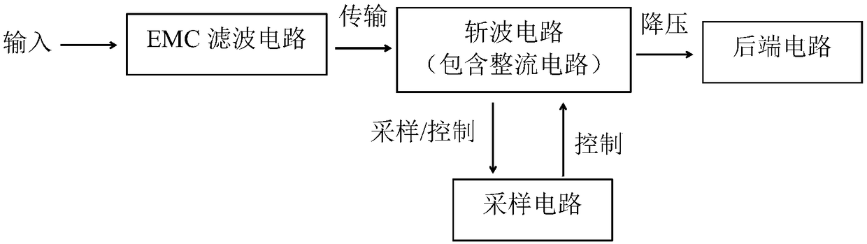
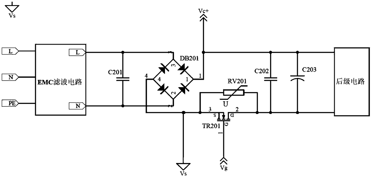
[0056] figure 2 The principle of the chopping circuit for the first embodiment of the present invention Figure 1 , including: a capacitor C201, a rectifier bridge DB201, a capacitor C202, a varistor RV201, a switching device and an energy storage module. In this embodiment, the switching device is an N-channel MOS transistor TR201.

[0057] The capacitors C201 and C202 are safety capacitors, the Vds of the N-channel MOS transistor TR201 is recommended to be above 650V, and the energy storage module selects the energy storage capacitor C203.

[0058] Both ends of the safety capacitor C201 are connected to the front-end EMC filter circuit L and N terminals, and are respectively connected to two AC input terminals of the rectifier bridge DB201: the first input terminal and the second input terminal, and the source of the MOS transistor TR201 (S ) is connected to the negative pole of the rectifier bridge DB201, the drain (D) of TR201 is connected to the negative pole of the ene...

no. 2 example

[0076] Figure 4.2 It is the principle diagram of the sampling circuit 2 of the second embodiment of the present invention, wherein the dotted box A is a stable power supply circuit, and the dotted box B is an input voltage detection circuit, and the sampling circuit includes: input voltage detection, a stable power supply circuit, a control chip U1, a voltage regulator Diodes D402 and D403, capacitor C401.

[0077] The input voltage detection circuit includes resistors R404, R403 and diode D404;

[0078] The stable power supply circuit includes resistors R401, R402 and diode D401.

[0079] There are 3 parts of the chopper circuit connected to the sampling circuit, such as figure 2 and Figure 4.2 As shown, where Vc+ is the anode of the sampling rectifier bridge DB201, and is transmitted to the sampling circuit for processing. The negative pole of the rectifier bridge DB201 outputs a Vs signal, which is used as the signal ground of the sampling circuit, and the positive p...

no. 3 example

[0086] Figure 5 is the principle of the chopper circuit in the third embodiment of the present invention Figure 1 , with the first example figure 2 The difference is that the switching device is changed from N-channel MOS transistor TR201 to P-channel MOS transistor TR202, and the connection relationship is adjusted as follows: the gate of TR202 is connected to the control signal Vg output by the sampling circuit, and the source of TR202 is connected to the rectifier The anode of the bridge DB201 and the drain of the TR202 are connected to the anode of the energy storage capacitor C203. Both ends of RV201 are connected in parallel between the source and drain of TR202. The connection relationship of other components remains unchanged. At the same time, the sampling circuit is properly adjusted and isolated.

[0087] Figure 6 is the principle of the chopper circuit in the third embodiment of the present invention Figure II , with the first example image 3 The diffe...


PUM


Abstract

The invention discloses an input overvoltage protection circuit. The circuit is capable of monitoring the size of DC voltage after the rectification of AC input voltage in real time and controlling the on/off of a switching element in a chopper circuits through a sampling circuit. When the AC input voltage is abnormally high, the sampling circuit is capable of rapidly detecting and controlling theswitching element in the chopper circuit to be located in an on/off state and freely setting an on overvoltage protection threshold value and an off overvoltage protection threshold value to maintainthe voltage size of an energy storage capacitor, so as to rapidly and effectively protecting a post circuit, prevent an energy storage capacitor and a switch tube in the post circuit from being damaged by overvoltage and enable the post circuit to continue the normal work. The input overvoltage protection circuit is suitable for the condition or occasion of three-phase four-wire AC voltage inputor single-phase AC voltage input which possibly has grounding faults to cause abnormal overvoltage of power grids, is high in reaction speed, simple and reliable in circuit, low in cost, excellent inEMC performance and flexible in design, and is capable of adjusting the on overvoltage protection threshold value and the off overvoltage protection threshold value.

Description

technical field [0001] The invention relates to the field of circuits, in particular to an input overvoltage protection circuit used in automatic power supply systems of three-phase four-wire and feeder grids. Background technique [0002] In the three-phase four-wire power meter and switching power supply in the feeder automation industry, problems such as ground faults and high-power equipment interference are often encountered, resulting in abnormally high grid voltage for a period of time. At this time, the grid voltage will exceed the switching power supply. The upper limit of the withstand voltage can easily cause damage to the switching power supply or even cause a fire, posing a huge safety hazard. [0003] There are mainly three methods for the existing switching power supply to solve the problem of high grid voltage, one is to increase the input overvoltage protection circuit, the second is to increase the upper limit of the working voltage range that the power sup...

Claims


Application Information

Patent Timeline
Patent Type & Authority Applications(China)
IPC IPC(8): H02H7/125
CPCH02H7/1252
Inventor 马晓彬周灿荣翁斌
Owner MORNSUN GUANGZHOU SCI & TECH
Why Eureka
Try Eureka