Piezoelectric skin detector

A detector, piezoelectric technology, applied in the field of biosensors and piezoelectric sensing, can solve the problems of inability to characterize the mechanical properties of nerve tissue, lack of miniaturized skin detection devices, unsuitable for home use and miniaturization, etc. Achieve the effect of rich detection information, good human-machine/human coupling, and not easy to be interfered by the outside world

Pending Publication Date: 2019-03-12
NANJING UNIV OF AERONAUTICS & ASTRONAUTICS
View PDF6 Cites 4 Cited by
  • Summary
  • Abstract
  • Description
  • Claims
  • Application Information

AI Technical Summary

Problems solved by technology

The advantage of in vitro measurement is that the isolated skin can be made into any desired shape for experiments, and the skin can be treated in layers to study the mechanical properties of each layer of the skin separately. In addition, the isolated skin can also be used to study the ultimate load and skin damage. Mechanism, etc., but due to the extremely complex structure of skin tissue, besides collagen fibers, subcutaneous fat, pores and other structures, it also has a large amount of nerve tissue. Therefore, in vitro measurement cannot characterize the influence of nerve tissue on mechanical properties, and this method is an invasive test with limited detection range and effect
[0004] As a widely used detection method for non-invasive living body measurement, the imprint method has been widely recognized in clinical medicine for its accuracy and reliability. Related instruments are also used in clinical detection, but due to the high cost of use and the need for professional training, it is not Suitable for home use and miniaturization, which limits the popularity of its use
[0005] In summary, there is a lack of a skin detection device that is miniaturized and capable of non-invasive living body measurement in the prior art.

Method used


Image

  • Piezoelectric skin detector
  • Piezoelectric skin detector
  • Piezoelectric skin detector

Examples


Embodiment Construction

[0031] In order to enable those skilled in the art to better understand the technical solutions of the present invention, the present invention will be further described in detail below in conjunction with specific embodiments.

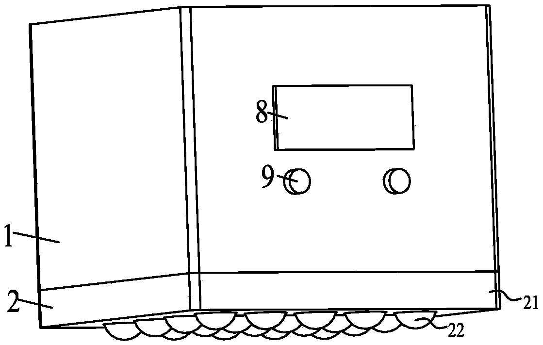
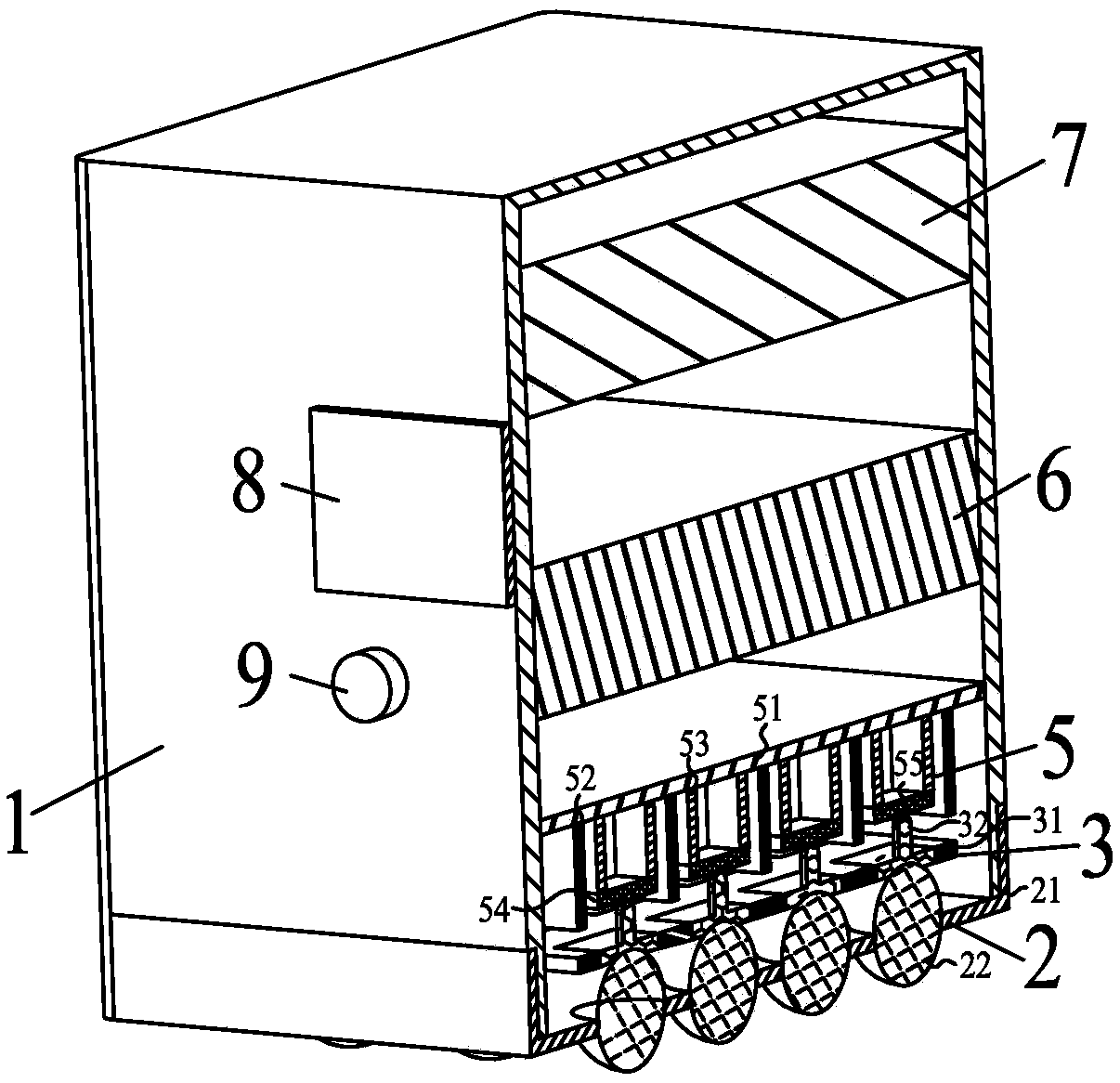
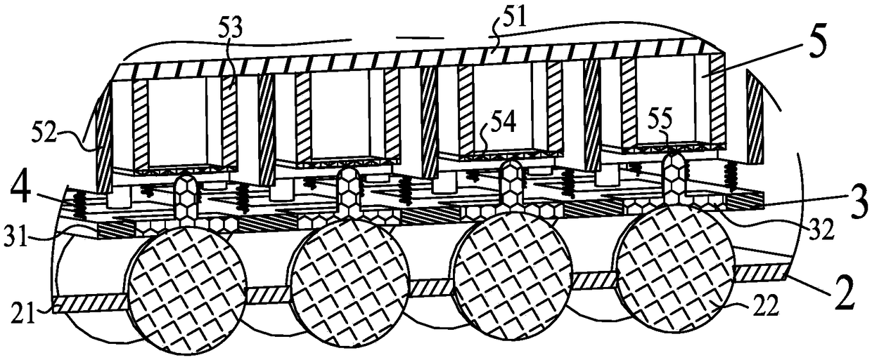
[0032] Embodiments of the present invention provide a piezoelectric skin detector, such as figure 1 , as shown in 2, including: including shell 1, probe 2, conductive component 3, return spring 4, sensing component 5, signal acquisition module 6, information feedback and control component 7, information display component 8, data transmission and conversion interface 9.

[0033] The probe 2 is installed at the bottom of the shell 1, and the probe 2 includes a probe bead holder 21 and a probe bead 22. On the probe bead holder 21 , there are arrays of probe bead installation and positioning holes for installing and positioning the probe beads 22 , and the probe 2 is fixedly connected to the housing 1 through the probe bead holder 21 .

[0034] The cond...


PUM


Abstract

The invention discloses a piezoelectric skin detector, and relates to the technical field of biological sensor and piezoelectric sensing. Non-invasive living body measuring of a small measuring devicecan be realized. The piezoelectric skin detector comprises a probe, a conduction assembly, a sensing assembly and a signal collecting module. One end of the probe makes contact with a to-be-measuredsurface, and the other end of the probe makes contact with the conduction assembly. The conduction assembly is connected with the sensing assembly in a clinical contact state. The sensing assembly isconnected with the signal collecting module. The probe transmits contact body surface conditions to the sensing assembly through the conduction assembly. The sensing assembly generates output signalsthrough the contact input signals. The signal collecting module collects the output signals of the sensing assembly. Through the positive piezoelectric effect, non-invasive detection of skin state information is realized, some physical and chemical information in skin is converted into charge or voltage information, auxiliary reference is provided for representing the physiological state of skin,and the piezoelectric skin detector has the advantages of being simple in structure, rapid in response, rich in detection information, high in comfort, free of invasion and the like.

Description

technical field [0001] The invention relates to the technical fields of biological sensors and piezoelectric sensing, in particular to a piezoelectric skin detector. Background technique [0002] The skin surface is a mirror of the physiological health of the human body. Through the detection and feedback analysis of the performance parameters of the skin tissue, it can provide a reference for qualitative and quantitative evaluation of the current state of the skin. As the largest tissue and organ of the human body, the skin is the medium for the exchange between the human body and the external environment. It has complex physiological functions and is affected by many factors such as body fluids, metabolism, and physical and chemical environments. The realization of the physiological functions of the skin depends on its biomechanical properties. , such as viscoelasticity, tension, compression resistance, etc. Detecting the biomechanics, shape, size, position and other char...

Claims


Application Information

Patent Timeline
Patent Type & Authority Applications(China)
IPC IPC(8): A61B5/00
CPCA61B5/441A61B5/6813
Inventor 刘鹏展陈金燕胡捷胡俊辉
Owner NANJING UNIV OF AERONAUTICS & ASTRONAUTICS
Why Eureka
Try Eureka