Driving circuit of silicon-carbide semiconductor field-effect transistor

A field effect tube and drive circuit technology, applied in the field of silicon carbide semiconductor field effect tube drive circuit, can solve the problems of reduced switching speed, increased current overshoot, fast switching speed, etc., to reduce current peaks and accelerate rising speed , Improve the effect of opening speed

Active Publication Date: 2019-03-19
HUAZHONG UNIV OF SCI & TECH
View PDF7 Cites 18 Cited by
  • Summary
  • Abstract
  • Description
  • Claims
  • Application Information

AI Technical Summary

Problems solved by technology

[0003] However, the traditional SiC MOSFET drive circuit has a contradiction between switching speed and current overshoot during the turn-on process. The traditional SiC MOSFET controls the switching speed and current overshoot by controlling the gate resistance. When the gate resistance is large, The current overshoot will decrease, but the switching speed will also decrease; conversely, when the gate resistance is small, the switching speed will increase, but the current overshoot will increase
Therefore, the traditional SiC MOSFET drive circuit cannot meet the requirements of fast switching speed and small current peak at the same time, and the drive circuit needs to be improved

Method used


Image

  • Driving circuit of silicon-carbide semiconductor field-effect transistor
  • Driving circuit of silicon-carbide semiconductor field-effect transistor
  • Driving circuit of silicon-carbide semiconductor field-effect transistor

Examples


Embodiment Construction

[0035] In order to make the object, technical solution and advantages of the present invention more clear, the present invention will be further described in detail below in conjunction with the accompanying drawings and embodiments. It should be understood that the specific embodiments described here are only used to explain the present invention, not to limit the present invention.

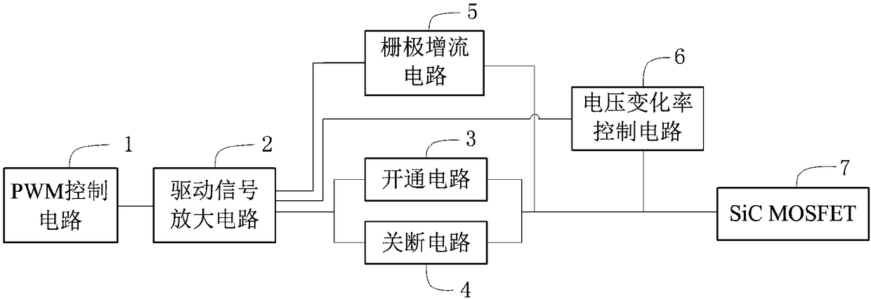
[0036] Such as figure 1 As shown, a driving circuit of a silicon carbide semiconductor field effect transistor according to the present invention includes: a PWM control circuit 1, a driving signal amplifying circuit 2, an opening circuit 3, an closing circuit 4, a gate current increasing circuit 5 and a voltage change rate control circuit 6;

[0037] The output end of the PWM control circuit 1 is connected to the input end of the drive signal amplifier circuit 2, and the drive signal amplifier circuit 2 is controlled to output a positive drive voltage and a negative drive voltage;

[0038] Th...


PUM


Abstract

The invention discloses a driving circuit of a silicon-carbide semiconductor field-effect transistor. The driving circuit comprises a PWM control circuit, a driving signal amplifying circuit, an opening circuit, a turning-off circuit, a gate current-increasing circuit and a voltage change rate control circuit. With the gate current-increasing circuit, the driving current is increased during the opening process of the SiC MOSFET and the rising of the gate-source voltage of the SiC MOSFET is accelerated, so that the opening speed of the SiC MOSFET is increased. With the voltage change rate control circuit, the Miller capacitance between the SiC MOSFET drain and gate is enhanced and the SiC MOSFET drain-source voltage change rate is reduced, so that the current spike during opening of the SiCMOSFET is reduced. After the SiC MOSFET drain-source voltage does not change, a voltage control switch is turned off to avoid the SiC MOSFET false conduction caused by the crosstalk, so that the safeoperation of the SiC MOSFET is ensured.

Description

technical field [0001] The invention belongs to the technical field of power electronics drive, and more specifically relates to a drive circuit for a silicon carbide semiconductor field effect transistor. Background technique [0002] SiC MOSFET (Metal-Oxide-Semiconductor Field-Effect Transistor) is a silicon carbide metal-oxide semiconductor field effect transistor, which has the advantages of fast switching speed, low switching loss, good temperature performance, high withstand voltage level, and small size. The field of electronic converters has very good application prospects, and high frequency is the development trend of power electronic conversion technology, but due to the fast switching speed of SiC MOSFETs, it is easily affected by various parasitic parameters in high frequency applications, resulting in oscillation , Misleading and other phenomena. Therefore, in practical applications, corresponding driving circuits must be designed to ensure the safe and reliab...

Claims


Application Information

Patent Timeline
Patent Type & Authority Applications(China)
IPC IPC(8): H02M1/08
CPCH02M1/08Y02B70/10
Inventor 孔武斌高学鹏甘醇曲荣海
Owner HUAZHONG UNIV OF SCI & TECH
Why Eureka
Try Eureka