Device for jointly testing internal force and external force of shield tunnel duct piece and manufacturing and burying method

A shield tunnel segment and joint testing technology, which is applied to measuring devices, tunnels, tunnel linings, etc., can solve problems such as water seepage accidents, long burying time, and difficult operations, and achieve strict cable protection measures and shorten burying time , the effect of low production cost

Inactive Publication Date: 2019-03-22
NINGBO UNIV +1
View PDF8 Cites 6 Cited by
  • Summary
  • Abstract
  • Description
  • Claims
  • Application Information

AI Technical Summary

Problems solved by technology

[0008] 2. The sensor thread cannot be soaked in water for a long time, otherwise the sensor will be invalid after water seeps into the sensor.
[0013] 1. There are three problems in the post-embedding method of the sensor that are difficult to solve: First, the embedding process is complicated, and the embedding time is too long, and the pre-embedded protective steel plate is prone to difficulty in dismantling the steel plate or damage to the installation chassis of the earth pressure sensor after dismantling, resulting in The earth pressure sensor cannot be placed in the segment. Such a long-term and complicated embedding method is not allowed by the segment production unit; second, the sensor post-embedment method needs to pass the cable through the segment, so it must be installed in the tube. The threaded pipe is reserved in advance, and the existence of the pipe is easy to make the segment leak; the third is that the sensor wire end cannot be buried in the segment, and the exposed wire end will cause the sensor to fail due to water immersion during the maintenance stage of the segment pool
[0014] 2. Although the invention of the monitoring rod can solve the above-mentioned three problems encountered by the sensor back-burying method, because it uses a strain gauge-type miniature earth pressure sensor, the test accuracy is affected by many factors such as temperature and cable length. Results are less reliable than vibrating wire sensors
In addition, piercing grouting holes on segments to embed sensors has strict requirements on the stratum. If it is implemented in strata with high water permeability, water seepage accidents may occur after the grouting holes are pierced, posing a serious threat to the operational safety of the tunnel.
[0015] 3. The sensor pre-embedding method can avoid the water immersion of the thread end and the water leakage of the segment, but this method has two disadvantages: first, the method requires welding to pre-embed the earth pressure sensor or the steel bar gauge in the steel cage, and the welding of the steel bar stress gauge It is also necessary to cut off the main reinforcement, and such embedding will take a long time; the second is that the earth pressure sensor buried by this method needs to expose the surface of the segment, and the surface of the segment must be smoothed for the needs of hoisting the segment, so that it must be After smoothing, it is very difficult to chisel off the concrete on the surface of the earth pressure sensor, and the earth pressure sensor is easily damaged
[0016] 4. The test items of the existing sensor embedding device are relatively single, and it is impossible to carry out risk assessment on the condition of the segment

Method used


Image

  • Device for jointly testing internal force and external force of shield tunnel duct piece and manufacturing and burying method
  • Device for jointly testing internal force and external force of shield tunnel duct piece and manufacturing and burying method
  • Device for jointly testing internal force and external force of shield tunnel duct piece and manufacturing and burying method

Examples


Embodiment 1

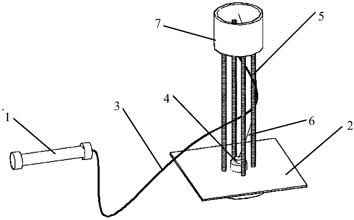
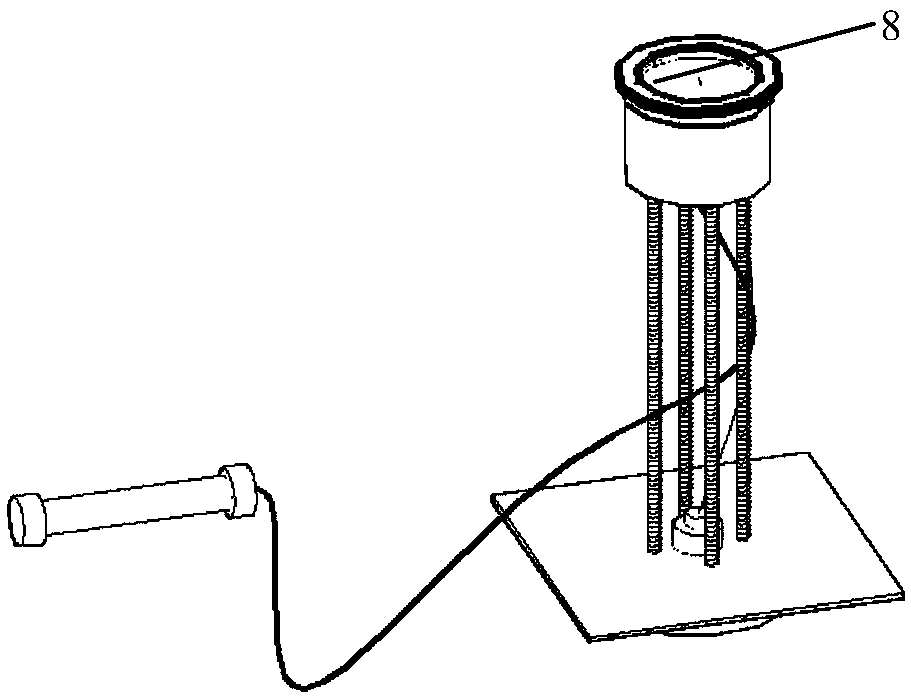
[0068] A combined test device for internal and external forces of a shield tunnel segment is mainly composed of a steel bar strain gauge, an earth pressure sensor, a water-stop steel plate, a cable protection box and a connecting screw. One end of the steel bar strain gauge 1 is connected to the steel bar strain gauge The cable 3 is connected to the steel cage 17 of the shield segment through the lead wire binding method. The steel bar strain gauge cable 3 passes through the cable protection box 7, and the cable protection box 7 is connected to the stopper through the connecting screw 5. The water steel plates 2 are connected, and an adjusting nut 11 and a gasket 16 are arranged between the connecting screw rod 5 and the cable protection box 7. The bottom surface of the cable protection box 7 is provided with a corresponding number of threading holes 10, and the top surface is provided with There is a cable protection box cover 8 and a protective sponge 20 at the bottom of the ...

Embodiment 2

[0081] The manufacturing and embedding method of the joint measurement device for the internal force of the shield tunnel segment and the external earth pressure of the segment is as follows:

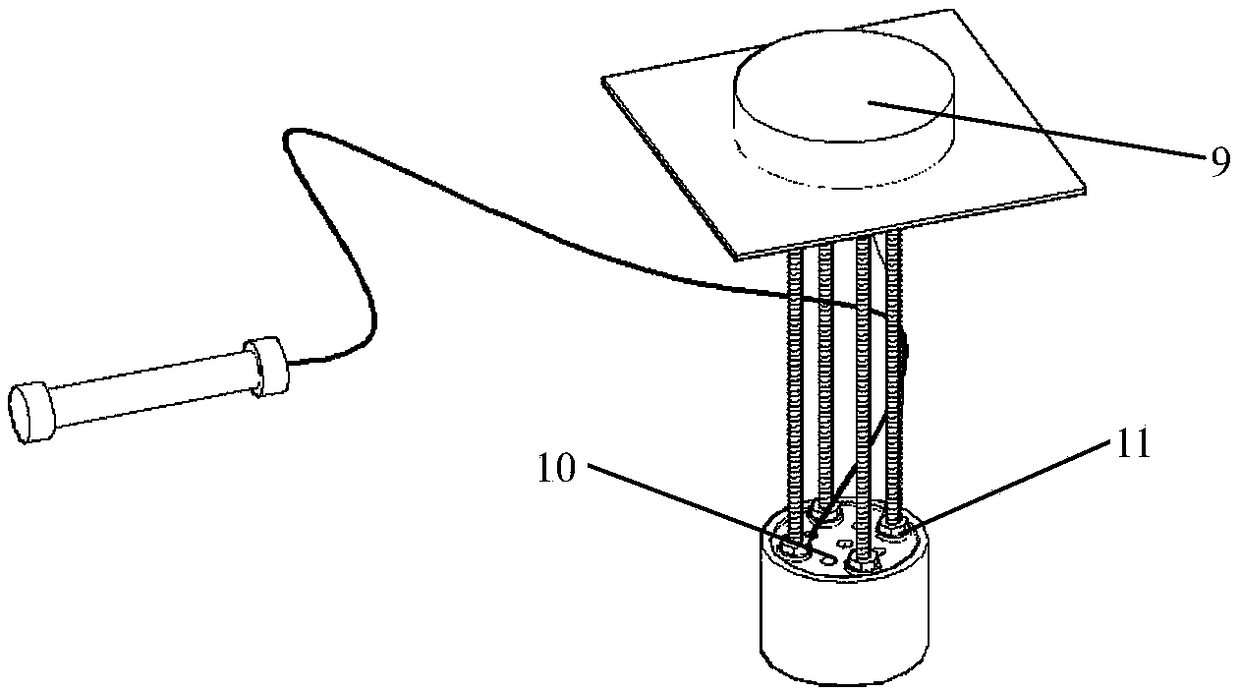
[0082] (1) Prepare a steel plate in advance, cut the steel plate into a square, and drill a hole in the center of the steel plate to make a water-stop steel plate 2 . Prepare a cover cable protection box 7 with a diameter of about 9 cm and a height of about 7 cm, drill four threading holes 10 with a diameter of 6 mm around the bottom of the steel bar strain gauge cable 3 protection box, and drill several holes with a diameter of 8 mm evenly distributed on other parts of the bottom surface. Small holes, the number of 8mm small holes is equal to the sum of the numbers of the earth pressure sensor 9 and the steel bar strain gauge 1 . Utilize the connecting screw 5 with a diameter of 6 mm to cut the screw into several small sections, the length of each section is the thickness of the segmen...

Embodiment 3

[0086] The test site is located in the section between Gaotangqiao Station and Jiangshan Station of Ningbo Rail Transit Line 3. The connecting passage in this section is constructed by mechanical method, that is, small shield construction is used. The small shield construction is provided by the main tunnel shield segment. Therefore, it is necessary to grasp the internal force and external earth pressure of the shield segment of the main tunnel in time during the construction of the small shield. The surrounding stratum conditions and sensor embedding conditions of the communication channel construction are as follows: Figure 15 , 16 shown.

[0087] After the tunnel shield segment is buried, the earth pressure outside the segment and the internal force of the segment are tested. The test results are as follows: Figure 17 As shown, the unit of earth pressure is kPa, and the unit of segment bending moment is kN·m. It can be seen from the test results that the present invent...


PUM

PropertyMeasurementUnit
thicknessaaaaaaaaaa
diameteraaaaaaaaaa

Abstract

The invention relates to a device for jointly testing an internal force and an external force of a shield tunnel duct piece. The device comprises a steel bar strain gauge, a soil pressure sensor, a water stop steel plate and a cable protection box and a connecting screw, wherein one end of the steel bar strain gauge is connected with a steel bar strain gauge cable and is connected with a duct piece steel bar cage through a galvanized wire binding method, the steel bar strain gauge cable penetrates through the cable protection box, the cable protection box is connected with the water stop steelplate through the connecting screw, an adjusting nut and a washer are arranged between the connecting screw and the cable protection box, a corresponding number of wiring holes are distributed in thebottom surface of the cable protection box, the top face of the cable protection box is provided with a cable protection box cover, the bottom of the cable protection box is provided with protectivesponge. The device has the advantages that the steel bar strain gauge of the device is connected with the duct piece steel bar cage through the galvanized wire binding method, accordingly the processes of steel bar cage cutting and welding of the steel bar strain gauge to a connecting rod are omitted, the embedding time of a duct piece prefabrication factory is greatly shortened, and the influenceon the production of the duct piece prefabrication factory is smaller.

Description

technical field [0001] The invention belongs to the field of geotechnical engineering testing, and in particular relates to a manufacturing and embedding method of a combined test device for the internal force of a shield tunnel segment and the external soil pressure of the segment. Background technique [0002] The shield method is the most common construction method for tunnel construction. Its working mechanism is that the cutter head of the shield machine is cut, the screw conveyor is unearthed, the hydraulic jack is pushed, and the segment assembly system is used to continuously assemble the standard prefabricated reinforced concrete segments. In order to form a lining tunnel structure system, each ring of the lining tunnel is connected by several segments through bolts, and the segments of each ring and adjacent rings are also connected by bolts, so that the entire tunnel is densely covered with segments and pipes. Sheet bolt connection points. Due to the existence of...

Claims


Application Information

Patent Timeline
Patent Type & Authority Applications(China)
IPC IPC(8): E21D11/08E21D11/38G01L5/00
CPCE21D11/08E21D11/38G01L5/0028
Inventor 周晔丁修恒姚燕明朱瑶宏刘干斌熊勇林
Owner NINGBO UNIV
Why Eureka
Try Eureka