Non-contact measurement device and method for sound velocities of surface waves and plate waves

A non-contact, measurement method technology, applied in measurement devices, using sonic/ultrasonic/infrasonic waves to analyze solids, and using sonic/ultrasonic/infrasonic waves for material analysis, etc. , application scope constraints, etc., to avoid human errors, strong signal processing and analysis functions, and easy system portability.

Pending Publication Date: 2019-03-26
NONGTAIKE KUNSHAN TEATING TECH CO LTD
View PDF10 Cites 6 Cited by
  • Summary
  • Abstract
  • Description
  • Claims
  • Application Information

AI Technical Summary

Problems solved by technology

At present, existing patents (Patent No.: ZL201210141763.9; ZL201210010938.2) and literature have proposed the use of contact wedge method and water immersion method to measure the sound velocity of surface waves and plate waves, but due to the limitations of coupling and specimen size Its application range is limited; and because it is impossible to accurately locate the distance between the measuring points or estimate the sound velocity by extracting the arrival of the first wave during the measurement, and there will be a process of gradual increase when the signal arrives, it is impossible to effectively judge the arrival time of the first wave leading to large experimental errors

Method used


Image

  • Non-contact measurement device and method for sound velocities of surface waves and plate waves
  • Non-contact measurement device and method for sound velocities of surface waves and plate waves
  • Non-contact measurement device and method for sound velocities of surface waves and plate waves

Examples


Embodiment 1

[0067] The device and method are used to detect the A0 mode plate wave velocity of an 8mm aluminum plate. The specific detection process is:

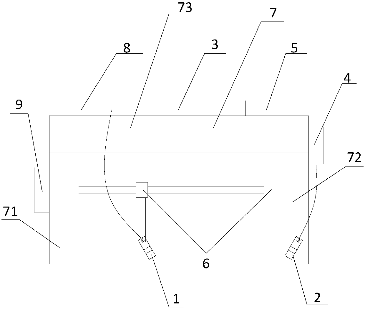
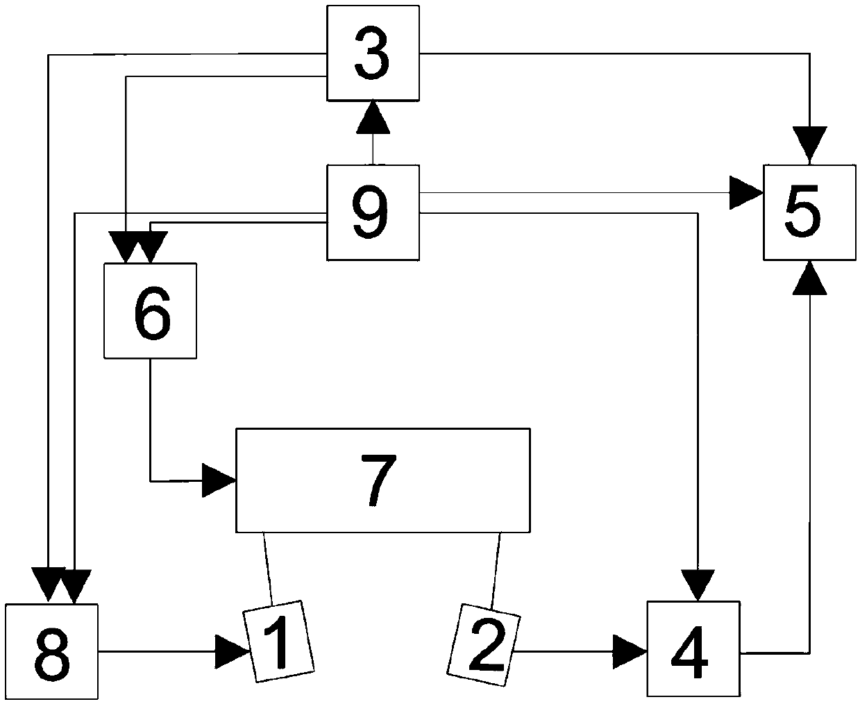
[0068] 1) Completely connect the entire detection device through the data cable and power on;

[0069] 2) Place the measured component under the scanning frame 7, and adjust the 50kHz probe to form a certain inclination angle with the measured component to meet the critical angle of incidence. After experiments, when the frequency thickness product is 5MHz·mm, the S0 and A0 modal plates The wave velocity tends to be consistent and becomes a surface wave. In this embodiment, the frequency-thickness product is 0.4MHz·mm, the incident angle is 11.5°, and the A0 mode plate wave is generated;

[0070] 3) The staff operates the embedded system 3 to make the pulse transmitter 8 continuously generate high-voltage pulse signals, and stimulate the transmitting probe 1 to generate ultrasonic waves;

[0071] 4) Observe the waveform to determine t...

Embodiment 2

[0079] The device and method are used to detect the surface wave velocity of an aluminum block. The specific detection process is:

[0080] 1) Completely connect the entire detection device through the data cable and power on;

[0081] 2) Place the component under test under the scanning frame 7, and adjust the 50kHz probe to form a certain inclination angle with the component under test to meet the critical angle of incidence;

[0082] 3) The staff operates the embedded system 3 to make the pulse transmitter 8 continuously generate high-voltage pulse signals, and stimulate the transmitting probe 1 to generate ultrasonic waves;

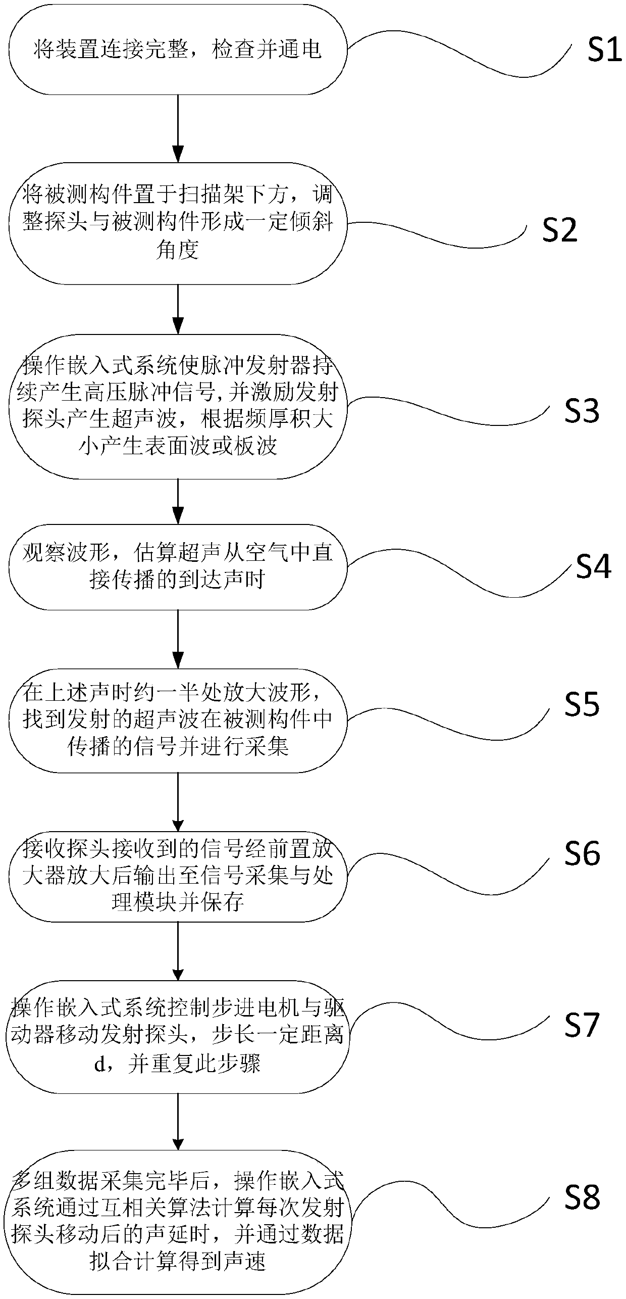
[0083] 4) Observe the waveform to determine the arrival time of the ultrasonic wave propagating from the air;

[0084] 5) Amplify the waveform at about half of the above sound time, find and collect the signal of the transmitted ultrasonic wave propagating in the component under test;

[0085] 6) The signal received by the acceptance probe 2 is amp...

Embodiment 3

[0091] The device and method are used to detect the A0 mode plate wave velocity of a 12mm steel plate. The specific detection process is:

[0092] 1) Completely connect the entire detection device through the data cable and power on;

[0093] 2) Place the component under test under the scanning frame 7, and adjust the 50kHz probe to form a certain inclination angle with the component under test to meet the critical angle of incidence;

[0094] 3) The staff operates the embedded system 3 to make the pulse transmitter 8 continuously generate high-voltage pulse signals, and stimulate the transmitting probe 1 to generate ultrasonic waves;

[0095] 4) Observe the waveform to determine the arrival time of the ultrasonic wave propagating from the air;

[0096] 5) Amplify the waveform at about half of the above sound time, find and collect the signal of the transmitted ultrasonic wave propagating in the component under test;

[0097] 6) The signal received by the receiving probe 2 ...


PUM


Abstract

The invention discloses a non-contact measurement device and method for sound velocities of surface waves and plate waves. The non-contact measurement device comprises an emitting probe, a receiving probe, an embedding system, a pre-amplifier, a signal collecting and processing module, a motor driving device, a scanning frame, a pulse emitter and a power supply, wherein the power supply is connected with the scanning frame, the pre-amplifier, the signal collecting and processing module, the motor driving device, the pulse emitter and the embedding system, respectively; the scanning frame is connected with the embedding system, the signal collecting and processing module, the motor driving device and the pulse emitter, respectively; the emitting probe is connected with the pulse emitter; the receiving probe is connected with the pre-amplifier; the embedding system is connected with the signal collecting and processing module, the motor driving device and the pulse emitter, respectively;the pre-amplifier is connected with a pulse amplifier and the signal collecting and processing module; the signal collecting and processing module is connected with the pre-amplifier and the embedding system; and the motor driving device is connected with the embedding system.

Description

technical field [0001] The invention relates to the field of ultrasonic testing, in particular to a non-contact measuring device and method for sound velocity of surface waves and plate waves. Background technique [0002] Ultrasonic testing is one of the most conventional non-destructive testing methods. Because it has a series of characteristics such as high sensitivity, strong penetrating power, good directivity, fast detection speed, low cost, relatively simple equipment, and harmless to the human body, it is widely used in the industry. field has been widely used. The conventional ultrasonic testing method is the contact type, that is, oil, colloid or other liquid must be used as the acoustic coupling agent between the ultrasonic probe and the test piece. These coupling agents need to be cleaned after detection, which usually affects the work of the entire system or makes the workplace get messy. One disadvantage of using liquid or dry coupling is that it usually requ...

Claims


Application Information

Patent Timeline
Patent Type & Authority Applications(China)
IPC IPC(8): G01N29/04G01N29/14G01N29/24
CPCG01N29/041G01N29/14G01N29/24
Inventor 潘永东赵仲杰
Owner NONGTAIKE KUNSHAN TEATING TECH CO LTD
Why Eureka
Try Eureka