
Cooling system for plastic corrugated pipe equipment

A cooling system and bellows technology, which is applied to tubular items, other household appliances, household appliances, etc., can solve the problems of low cooling efficiency, high failure rate, limiting the production speed of pipes, etc., and achieve the effect of improving efficiency.

Pending Publication Date: 2019-03-29
潍坊中云科研有限公司
View PDF0 Cites 3 Cited by
  • Summary
  • Abstract
  • Description
  • Claims
  • Application Information

AI Technical Summary

Problems solved by technology

However, the current water-cooling scheme for corrugated forming modules either has the disadvantages of complex structure and high failure rate, resulting in frequent leakage of coolant, or has the disadvantage of being too simple in structure and low in cooling efficiency, making high-speed production impossible
[0005] The cooling method of air cooling or water cooling alone has certain limitations on the cooling efficiency of the pipe, especially the cooling efficiency of the online flaring pipe is too low, because the pipe is not cooled properly, it will cause the pipe to deform and cannot be used, so it must be reduced The production speed of the pipe is to ensure that the pipe is fully cooled and formed, which seriously limits the improvement of the pipe production speed

Method used


Image

  • Cooling system for plastic corrugated pipe equipment
  • Cooling system for plastic corrugated pipe equipment
  • Cooling system for plastic corrugated pipe equipment

Examples


Embodiment Construction

[0031] The technical solution of the present invention will be described in detail below in conjunction with the accompanying drawings and specific embodiments to further understand the purpose, solution and effect of the present invention, but it is not intended to limit the scope of protection of the appended claims of the present invention.

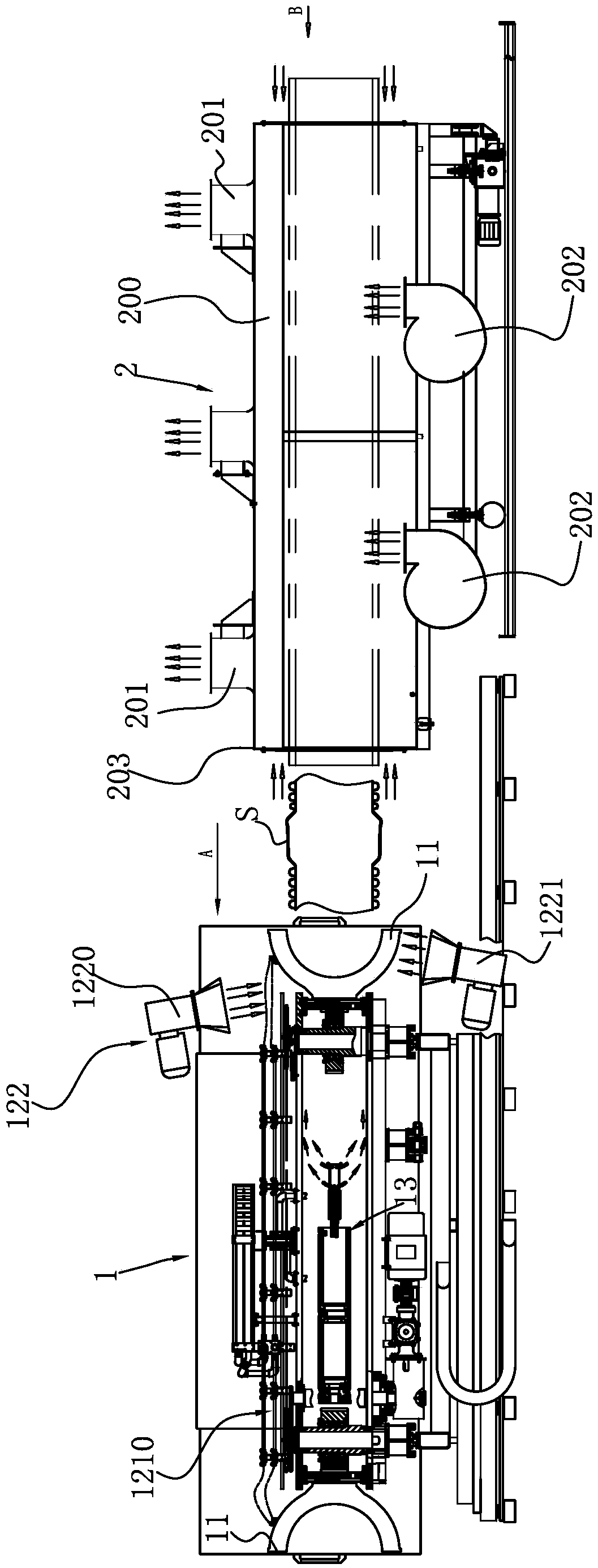
[0032] combine figure 1 A brief description of the manufacturing process of the plastic bellows: the plastic raw material is first heated and plasticized by the plastic extruder, and then transformed into a molten state. The molten plastic material passes through the extrusion head, and the extrusion head extrudes two Tube blanks with different diameters in the shape of tubes, the large-diameter tube blank is the outer wall of the tube, and the small-caliber plastic tube blank is the inner wall of the tube. After the tube blank enters the bellows forming device 1, the outer tube blank passes through compressed air and vacuum. Working t...


PUM


Abstract

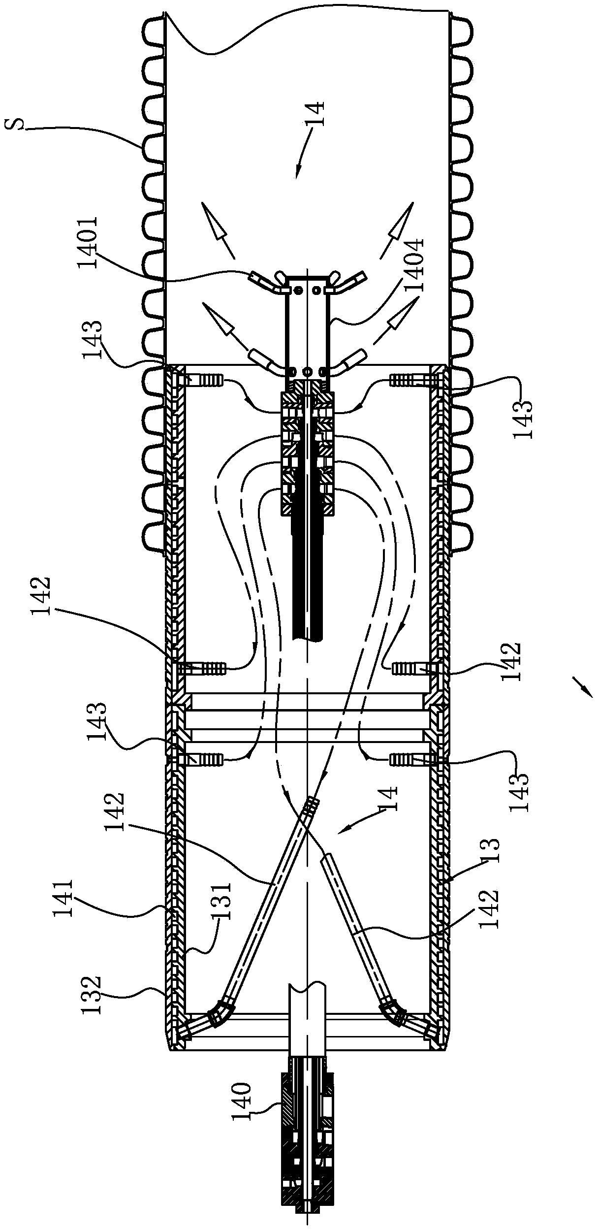
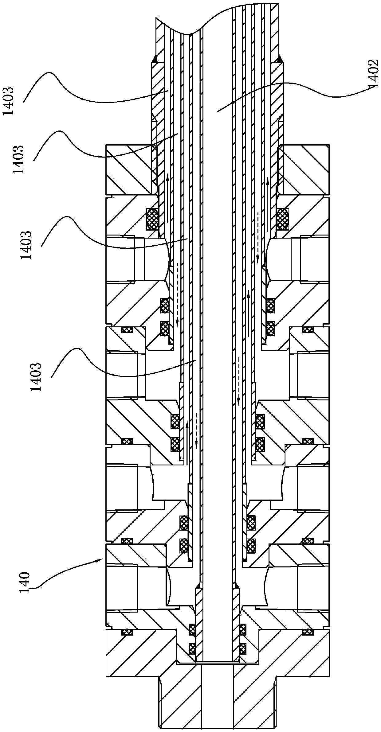
The invention discloses a cooling system for plastic corrugated pipe equipment. The cooling system for the plastic corrugated pipe equipment comprises a molding module cooling device which is arrangedon a molding module and a diameter fixing sleeve cooling device which is arranged on a diameter fixing sleeve, wherein the diameter fixing sleeve cooling device comprises a main pipeline assembly which is provided with a water channel and an air channel; the main pipeline assembly passes through an inner cavity of the diameter fixing sleeve in the axial direction; the inner part of the peripheralwall of the diameter fixing sleeve is provided with a diameter fixing sleeve cooling water channel; a plurality of diameter fixing sleeve water distribution pipe groups are connected between the diameter fixing sleeve cooling water channel and the main pipeline assembly; a plurality of air outlets which communicate with the air channel are formed in the tail end of the main pipeline assembly; andthe molding module cooling device comprises a molding module water cooling device and a molding module air cooling device. The inner wall and the outer wall of a corrugated pipe are cooled through the diameter fixing sleeve cooling device and the molding module cooling device, so that the inner wall and the outer wall of the corrugated pipe are quickly cooled, and the plastic corrugated pipe is further cooled through a corrugated pipe secondary air cooling device, so that the plastic corrugated pipe is quickly cooled, subsequent cutting is convenient to carry out, and the production efficiency of the plastic corrugated pipe is improved.

Description

technical field [0001] The invention relates to equipment for manufacturing plastic bellows, in particular to a cooling system for plastic bellows equipment. Background technique [0002] The full name of HDPE in English: "High Density Polyethylene", the Chinese name is high-density polyethylene, which is a high-crystallinity, non-polar thermoplastic resin. The plastic pipe made of HDPE has reliable connection and good low-temperature impact resistance. , Good stress crack resistance, good chemical corrosion resistance, good aging resistance, good wear resistance, good toughness, high pressure resistance and long service life. Compared with traditional pipes such as cast iron pipes and galvanized steel pipes, HDPE plastic pipes have significant advantages such as light weight, corrosion resistance, small water flow resistance, energy saving, easy and fast installation, and low cost. They are loved by the pipeline engineering community. And gradually replace the traditional ...

Claims


Application Information

Patent Timeline
IPC IPC(8): B29C48/09B29C48/90B29C48/88B29C48/885B29L23/18
CPCB29L2023/18
Inventor 张泽奎张善友齐延磊
Owner 潍坊中云科研有限公司
Learn More