Manufacturing method for skeleton-free niobium-tri-tin superconducting coil

A technology for superconducting coils and manufacturing methods, applied in coil manufacturing, inductance/transformer/magnet manufacturing, electrical components, etc., capable of solving problems such as deformation of niobium-three-tin superconducting coils and reduction of total current density of niobium-three-tin superconducting coils , to achieve superior electrical insulation performance, excellent thermal stability, and reduce cooling capacity

Active Publication Date: 2019-03-29
INST OF ELECTRICAL ENG CHINESE ACAD OF SCI
View PDF8 Cites 3 Cited by
  • Summary
  • Abstract
  • Description
  • Claims
  • Application Information

AI Technical Summary

Problems solved by technology

[0007] The purpose of the present invention is to overcome the problem of deformation of the niobium-three-tin superconducting coil wound by stainless steel framework in the prior art during long-term high-temperature heat treatment, and the problem that the framework itself will reduce

Method used


Image

  • Manufacturing method for skeleton-free niobium-tri-tin superconducting coil
  • Manufacturing method for skeleton-free niobium-tri-tin superconducting coil
  • Manufacturing method for skeleton-free niobium-tri-tin superconducting coil

Examples


Example Embodiment

[0034] Example one

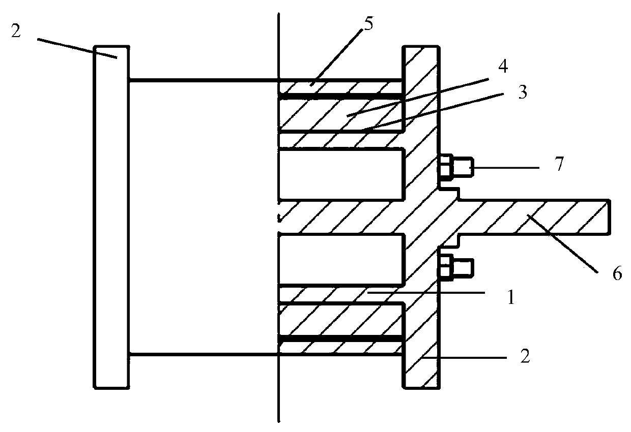
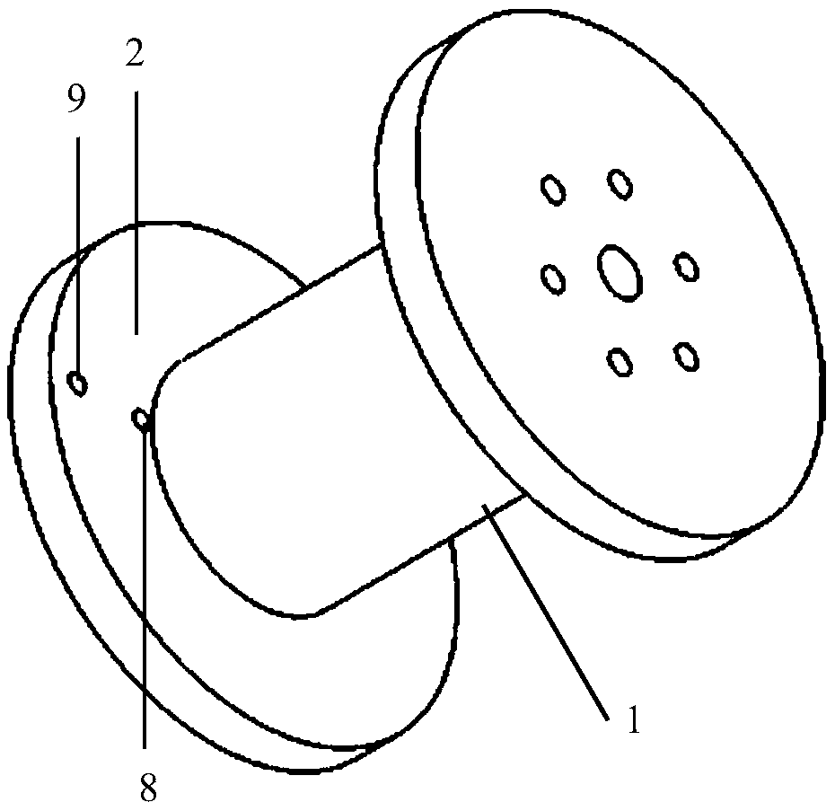
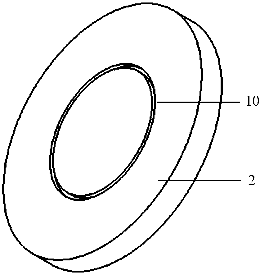
[0035] Connect the cylindrical quartz tube 1 with the two end plate flanges 2, and open a circular groove at the junction of the two end plate flanges 2 and the cylindrical quartz tube 1, and the cylindrical quartz tube 1 is clamped into the circular groove 10 . A through hole is opened in the center of the flange 2 of the two end plates, and an M6 screw 6 is installed in the through hole. A circle of through holes is opened in the circumferential direction where the flange 2 of the two end plates and the inner surface of the cylindrical quartz tube 1 are tangent, and the number of through holes is three. Three through holes are installed with three M4 screws 7 for positioning and clamping, so that the center of the cylindrical quartz tube 1 and the two end plate flanges 2 are aligned and firmly connected. Install the assembled quartz skeleton on the winding machine. On the outer surface of the cylindrical quartz tube, two layers of glass cloth 3 are wrapp...

Example Embodiment

[0037] Example two

[0038] The cylindrical quartz tube 4 is connected with the two end plate flanges 2 through the annular grooves 10 on the two end plate flanges 2. A screw 6 is installed at the center of the flanges of the two end plates, and fixed with nuts at both ends. There is a through hole in the center of the flange of the two end plates, and an M20 screw 7 is installed in the through hole. The two end plates 2 and the inner surface of the cylindrical quartz tube 1 are respectively provided with a circle of through holes in the circumferential direction, and the number of through holes is 6. Six M4 screws 7 are installed in the through holes for positioning and clamping, so that the cylindrical quartz tube 1 and the two end plate flanges 2 are centered and firmly connected. Install the assembled quartz skeleton on the winding machine. On the outer surface of the cylindrical quartz tube, two layers of glass cloth 3 are wrapped in half. Enter the wire in the wire entr...


PUM


Abstract

A manufacturing method for a skeleton-free niobium-tri-tin superconducting coil is disclosed. According to the method, a cylindrical quartz tube (1) and two end plate flanges (2) are assembled by nutfixation to be a skeleton for wrapping wires; a quartz skeleton is mounted on a winding machine to wind a niobium-tri-tin wire superconducting wire; when the wire is changed between layers, a layer ofglass wool cloth is laid on the surface of the upper layer of the niobium-tri-tin wire superconducting wire; after winding of a niobium-tri-tin superconducting coil (4) is completed, a wire is discharged at a wire outlet hole (9) of an end plate; the glass wool cloth is wrapped around the outermost layer of the niobium-tri-tin superconducting coil (4) in a half-lapping manner; then a binding layer (5) is wound around the outermost side; after the winding of the binding layer (5) is completed, the niobium-tri-tin superconducting coil equipped with tooling is placed in a vacuum heat treatment furnace for performing vacuum heat treatment and vacuum pressure impregnation, and finally an epoxy resin curing process is performed; and after the curing, the quartz tube (1) is removed to obtain theniobium-tri-tin superconducting coil (4) containing no skeleton.

Description

technical field [0001] The invention relates to a manufacturing method of a superconducting coil. Background technique [0002] The resistance of the superconducting wire is zero at a certain critical temperature. After the superconducting wire is wound into a superconducting coil, it can withstand a large current at the critical temperature, thereby generating a strong magnetic field. Based on this characteristic of superconducting coils, superconducting magnets can be designed and manufactured, and the number of layers and turns of superconducting coils can be designed according to the required magnetic field size and uniformity. A superconducting magnet is composed of superconducting coils of various shapes. The most common superconducting coil is a solenoid-shaped superconducting coil, in which a superconducting wire is wound on a cylindrical skeleton. Generally, superconducting magnets that generate strong magnetic fields are nested and combined with superconducting co...

Claims


Application Information

Patent Timeline
IPC IPC(8): H01F41/04H01F41/098H01F41/12
CPCH01F41/048H01F41/098H01F41/127
Inventor 孙万硕王秋良程军胜刘建华王磊孙金水刘辉王晖
Owner INST OF ELECTRICAL ENG CHINESE ACAD OF SCI
Why Eureka
Try Eureka