Laser paint removing method for polyimide coating enameled wire

A polyimide coating, enameled wire technology, applied in the direction of circuit/collector parts, electrical components, circuits, etc., can solve the problems of long laser processing time, high power demand, high cost, reduce energy consumption, laser Effects of power reduction and low conversion efficiency

Active Publication Date: 2019-03-29
WUHAN LINGYUN PHOTOELECTRONICS SYST
View PDF5 Cites 6 Cited by
  • Summary
  • Abstract
  • Description
  • Claims
  • Application Information

AI Technical Summary

Problems solved by technology

Due to the good heat resistance and strong adhesion of polyimide paint, when using the traditional laser paint removal method to remove the paint from this enameled wire, it needs higher laser power and longer processing time, which will lead to the following Serious problems: the polyimide paint layer is excessively coked and adhered and cannot be cleaned, the inner copper wire cannot be exposed and cannot be tinned, the laser processing time is too long or the power demand is too high, which reduces the annealing and oxidation physical strength of the copper wire, and the use of high-power green laser Or the high cost of ultraviolet lasers makes it impossible to promote it on a large scale

Method used


Image

  • Laser paint removing method for polyimide coating enameled wire
  • Laser paint removing method for polyimide coating enameled wire
  • Laser paint removing method for polyimide coating enameled wire

Examples


Embodiment 1

[0047] A kind of laser depainting method of polyimide coated enameled wire provided by the invention, the steps are:

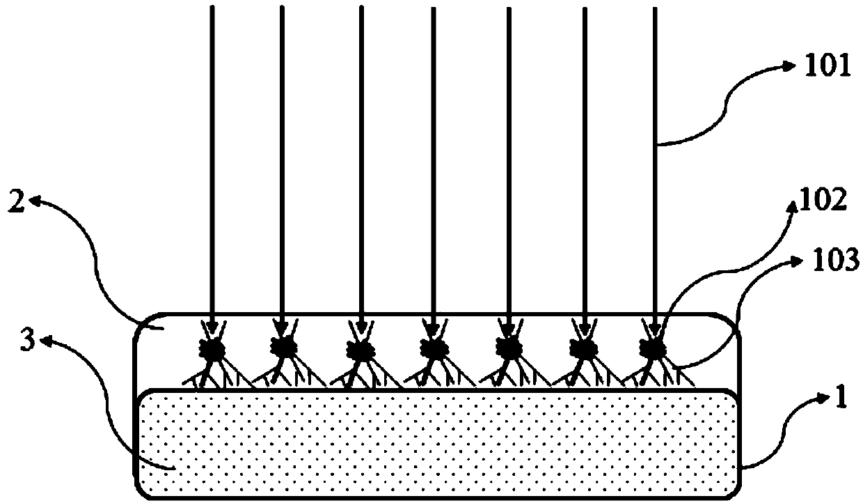
[0048] a. Surface pretreatment

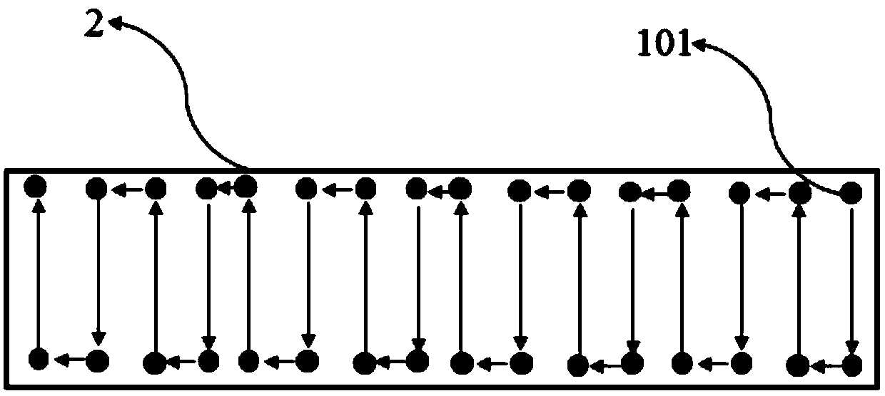
[0049] like Figure 1-2 As shown, use the ultraviolet laser to set the laser power of the first laser beam 101 to 5W and the frequency to 30KHz, adjust the first laser beam 101 to focus on the paint layer 2 of the enameled wire 1 to the smallest spot diameter, and scan the entire paint layer without crossing the path 2 Rough without visible smoothness, the scanning frequency of the first laser beam 101 is 1 time, and the scanning path is to scan alternately from the right end of the enameled wire to the left end in a U shape on both sides of the width, figure 2 The middle, left, and right directions are the length direction of the enameled wire 1, and the up and down directions are its width direction, and the following Figure 4 and Image 6 in the same way;

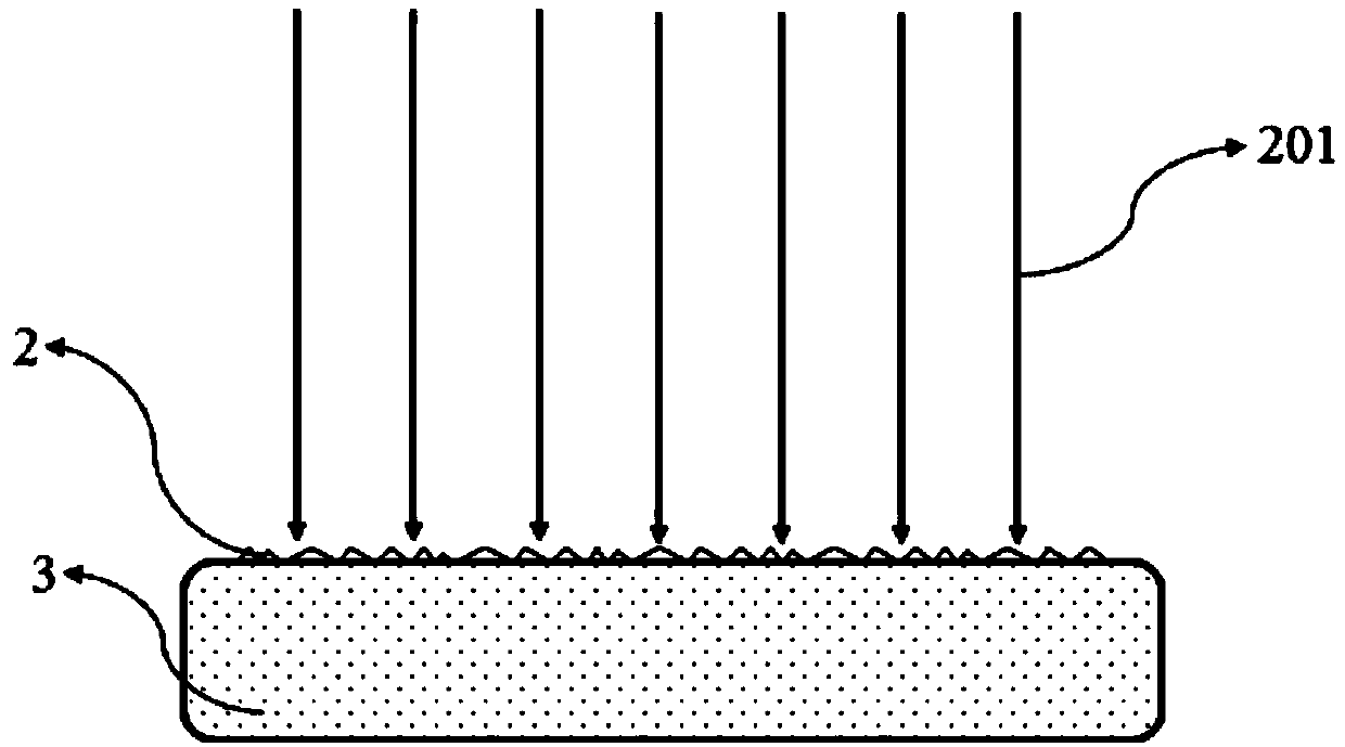
[0050] b. Heating to remove paint

[0051] like Figure 3-4 ...

Embodiment 2

[0057] Except the following parameters: the spot diameter of the second laser beam 201 is 1.4 times the width of the paint layer 2, the interval between two adjacent scans is 1 second, and the scan is repeated 8 times. The paint removal method of this embodiment is the same as that of Embodiment 1.

Embodiment 3

[0059] Except the following parameters: the spot diameter of the second laser beam 201 is 1.5 times the width of the paint layer 2, the interval between two adjacent scans is 5 seconds, and the scan is repeated 3 times. The paint removal method of this embodiment is the same as that of Embodiment 1.


PUM


Abstract

The invention discloses a laser paint removing method for a polyimide coating enameled wire. The laser paint removing method is characterized by comprising the following steps: a, surface pretreatment: adjusting a focusing of a first laser beam on a paint layer of the enameled wire until the diameter of a light spot is minimum, and scanning the path in a non-cross manner until the whole paint layer is rough, invisible and smooth; b, heating to remove paint, adjusting a second laser beam to focus on a paint layer of the enameled wire until the diameter of a light spot covers the paint layer inthe width direction, and scanning the whole paint layer for multiple times in the length direction of the enameled wire until the paint layer falls off; and c, performing surface treatment again to remove residual paint, adjusting a third laser beam to focus on a paint layer of the enameled wire until the diameter of a light spot is minimum in an inert gas environment, and performing multi-time path cross scanning until the natural color of the copper substrate of the whole enameled wire is completely exposed. The required laser power is reduced compared with that of a single laser wavelengthand a single processing step, and the laser power requirement for reducing the wavelength is advantageous for reducing the production cost and reducing the energy consumption.

Description

technical field [0001] The invention relates to the technical field of surface treatment, in particular to a method for removing polyamide resin insulation coatings on enameled wires by using lasers. Background technique [0002] Enameled wire is one of the important raw materials for making magnetic devices such as motors, inductors, and transformers. Especially with the emergence of a large number of consumer electronics products, the internal DC-DC DC conversion modules require a large number of high-current density inductors and pulse transformers for energy transmission. And energy storage devices and enameled wire is one of the basic materials for making such devices. The joints of enameled wires need to be devarnished and tinned. The conventional methods for removing the insulating varnish of enameled wires include mechanical grinding and chemical dissolution. Among them, the method of mechanical grinding will make the enameled wire thinner, and it is easy to cause b...

Claims


Application Information

Patent Timeline
Patent Type & Authority Applications(China)
IPC IPC(8): H01R43/28
CPCH01R43/28
Inventor 林卿
Owner WUHAN LINGYUN PHOTOELECTRONICS SYST
Why Eureka
Try Eureka