Pulse power synthesis circuit based on constant energy chopping technology

A pulse power and synthesis circuit technology, applied in the direction of output power conversion device, DC power input conversion to DC power output, electrical components, etc., can solve the problems of control circuit transmission loop interference, high voltage and current change rate, difficult control circuit Achieve the effects of low chopping frequency, low distortion and low distribution parameters

Pending Publication Date: 2019-03-29
HONGHE COLLEGE
View PDF0 Cites 0 Cited by
  • Summary
  • Abstract
  • Description
  • Claims
  • Application Information

AI Technical Summary

Problems solved by technology

[0005] The transmission mode of PWM converter is the characteristic of voltage transmission. If the output power is required to be constant, it is necessary to implement double closed-loop control of voltage and current at the load. This control mode is complicated and the control circuit is difficult to realize.
[0006] When synthesizing large power, the chopping frequency of the chopper bridge is high, and the rate of change of voltage and current is extremely high, the control circuit and transmission loop are greatly disturbed, resulting in the circuit not working normally, and the high chopping frequency makes The distribution parameters of the transformer also have a great influence on the interference of the circuit

Method used


Image

  • Pulse power synthesis circuit based on constant energy chopping technology

Examples


Embodiment Construction

[0032] Further illustrate the present invention below in conjunction with accompanying drawing.

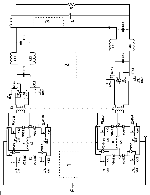
[0033] Such as figure 1 As shown, the calculation of parameters such as the specifications of field effect transistors and diodes, the size of capacitance, resistance, and inductance of the present invention is completely the same as that of the prior art, which is a mature technology and will not be discussed further.

[0034] Inductors L11~Ln1, L12~Ln2 are smoothing inductors; capacitors C11~Cn1, C12~Cn2 are smoothing capacitors; inductor L is a filter inductor, and capacitor C is a filter capacitor, which constitute an LC filter circuit.

[0035]Among them, the field effect tubes (K11, K12, K13, K14)... (Kn1, Kn2, Kn3, Kn4) respectively constitute the chopper circuit of the 1~n stage of the chopper circuit, and the inductance L1~Ln is the chopper circuit of the chopper circuit 1~n Level energy storage inductors, transformers T1~Tn and their FETs, smoothing inductors, and smoot...


PUM


Abstract

The invention discloses a pulse power synthesis circuit based on constant energy chopping technology. The pulse power synthesis circuit is composed of a chopper loop, a control loop, a transmission loop, and a synthesis loop. The chopper loop and the transmission loop have multiple stages and are connected in parallel between a power supply and the synthesis loop, the chopper loop and the transmission loop of the same stage are in coupling connection through a transformer of the same stage, and circuit structures of the chopper loop of each of the stages and the transmission loop of each of the stages are the same. Circuit components and connection relations of the synthesis loop are that: the right end of an inductor L and the upper end of capacitor C is connected to the upper end of a load R, the lower end of the capacitor C is connected to the lower end of the load R, the left end of the inductor L is an input upper end of the synthesis loop, and the lower end of the capacitor C isan input lower end of the synthesis loop; and two ends of the capacitor C are output ends of the synthesis loop. The pulse power synthesis circuit is adjustable in constant power output and the sizeof power and is adjustable in synthesis waveform frequency and low in waveform distortion factor, can make a switching device work in a soft switching state, does not damage main power devices when anoutput power circuit is short-circuited, and is large in load synthesis power.

Description

technical field [0001] The invention is a pulse power synthesis circuit based on constant energy chopping technology. Background technique [0002] In some precision machining occasions, such as medium-frequency motors, which require energy with constant frequency and high power, and ultra-high-speed drills, which require energy with constant power but high frequency, and both of the above two occasions require harmonics contained in the synthesized waveform. The wave component is low. When the current PWM technology combines power, the combined power cannot be adjusted. The frequency of the synthesized waveform is limited. 1. The interference of the load synthesis waveform is very serious, and the circuit faces the danger of overvoltage, overcurrent, overheating and damage to the power tube during operation. [0003] In the existing technology, the traditional PWM technology works in the way of voltage chopping, that is, the way of pulse width modulation to convert current...

Claims


Application Information

Patent Timeline
Patent Type & Authority Applications(China)
IPC IPC(8): H02M3/335H03K5/13
CPCH02M3/33507H03K5/13Y02B70/10
Inventor 谢鸿龄李娟段志梅蔡群李俊生刘祥明张英争
Owner HONGHE COLLEGE
Why Eureka
Try Eureka