
Rapid detecting device and method for latent fingerprint

A detection device, a potential technology, applied in the direction of measurement devices, material excitation analysis, fluorescence/phosphorescence, etc., can solve the problems of improving detection resolution, damage, and increasing detection range, so as to improve fluorescence collection efficiency and high fluorescence collection efficiency , The effect of improving the detection speed

Active Publication Date: 2019-04-05
SHANGHAI INST OF OPTICS & FINE MECHANICS CHINESE ACAD OF SCI
View PDF10 Cites 6 Cited by
  • Summary
  • Abstract
  • Description
  • Claims
  • Application Information

AI Technical Summary

Problems solved by technology

[0007] 1) The detection effect of the physical visualization method is poor, and the dust generated by the brush method and the harmful gas generated by the fumigation method will cause damage to the operator; some reagents and dyes such as rhodamine 6G in the chemical visualization method are toxic, and long-term exposure will affect health; The process of brushing and dyeing may cause irreversible damage to fingerprints and precious physical evidence
[0008] 2) The ultraviolet reflection imaging method uses the difference between the reflection and absorption of ultraviolet light on the surface of the fingerprint material and the test material to form a reflective ultraviolet light pattern of the fingerprint on the imaging objective lens; with the prolongation of the remaining time, the moisture and organic substances in the fingerprint will be reduced. Gradually volatilize or penetrate into the interior of the test material, and there are few fingerprints left on the surface of the test material, that is, the difference between the old fingerprint on the test material and the surface of the test material is small, so the ultraviolet reflection imaging method is not good for the detection of old latent fingerprints
[0009] 3) When using ultraviolet light-induced fluorescence imaging to detect potential fingerprints, due to the large ultraviolet laser spot and the low power density of the ultraviolet laser obtained on the test material, the fluorescence of potential fingerprints on the test material cannot be effectively excited, so there is a fingerprint detection rate Low, unable to achieve high-sensitivity detection of inspection materials and other issues
The problem with this detection method is that: the increase of the focal length of the flat-field scanning lens will increase the detection range, and also lead to the increase of the spot size on the test material; the size of the scanning galvanometer limits the incident beam aperture, that is, limits In order to obtain a smaller spot size on the inspection material, it is not conducive to improving the detection resolution; limited by the scanning galvanometer swing angle range and response speed, only a small range of detection can be achieved at a time, and the detection speed is limited; Large detection range and good detection effect, the flat-field scanning lens needs to adopt flat-field design, achromatic and object-space telecentric design, and the distortion of the flat-field scanning lens needs to be corrected, the design is complex and the device volume is large

Method used


Image

  • Rapid detecting device and method for latent fingerprint
  • Rapid detecting device and method for latent fingerprint
  • Rapid detecting device and method for latent fingerprint

Examples


Embodiment

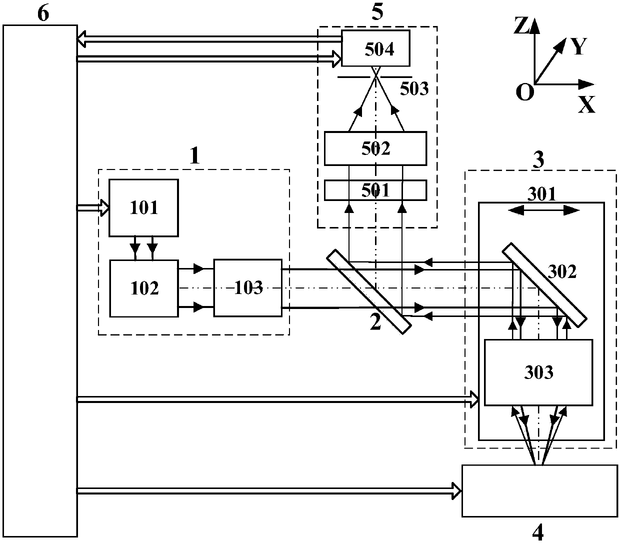
[0086] The schematic diagram of the structure of the device for quickly detecting latent fingerprints of the present invention is as follows: figure 1 As shown, it includes a light source and transmission module 1 , a dichroic mirror 2 , a flight scanning module 3 , a sample stage 4 , a fluorescence detection module 5 and a machine control module 6 .

[0087] The light source and transmission module 1 sequentially includes a laser 101, a beam transmission module 102, and a cylindrical lens 103; the flight scanning module 3 includes an optical module movement platform 301, a mirror 302, and a focusing and collimating lens group 303; The fluorescence detection module 5 includes a common optical axis narrow band filter 501 , a focusing lens 502 , a slit diaphragm 503 and a linear array photodetector 504 .

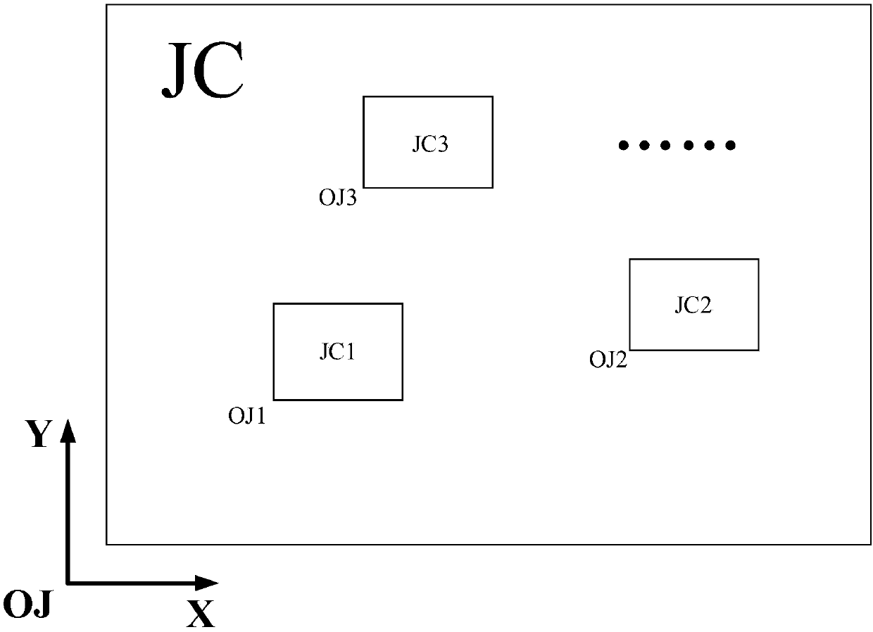
[0088] The schematic diagram of the large-scale inspection material of the present invention is as follows figure 2 As shown, in this embodiment, paper in the size range of ...


PUM

PropertyMeasurementUnit
reflectanceaaaaaaaaaa

Abstract

The invention discloses a rapid detecting device and method for a latent fingerprint. The rapid detecting device comprises a light source and transmitting module, a dichroic mirror, a flying scanningmodule, a sample platform, a fluorescence detection module and an overall machine control module; and the rapid detecting method comprises two modes of rough detecting and fine detecting, the rough detecting mode is used for rapidly positioning a suspicious fingerprint area on a detecting material, and the fine detecting mode is used for performing high-resolution detection on the suspicious fingerprint area to obtain precise fingerprint information. In the detecting process, a light source forms a one-dimension focal line on the detecting material, and a linear array detector is used for receiving fluorescence; and the light source and transmitting module, the dichroic mirror and the fluorescence detection module maintain to be stationary, and an optical module moving bearing platform drives a mirror and a focusing collimating mirror module to perform one-dimension flying scanning linear motion. According to the detecting device and method for the latent fingerprint, the detecting speed is high, an obtained fingerprint fluorescent image is not distorted, and the precision of the detecting result is improved.

Description

technical field [0001] The invention relates to the technical field of fingerprint detection, in particular to a rapid detection device and detection method for latent fingerprints. Background technique [0002] As the crime rate increases, how to effectively identify the personal information of criminal suspects has become a major concern of relevant departments. Fingerprints have the characteristics of being different from person to person, unchanged throughout life, and leaving traces when touched. They have the reputation of "human ID card" and "king of evidence". They are the most effective signs that distinguish individuals from others. play an important role. Common fingerprints are mainly divided into three categories: visible fingerprints, latent fingerprints and plastic fingerprints. Among them, latent fingerprints are invisible and are the most common type of fingerprints in life, which play an important role in solving cases. [0003] The traditional fingerprin...

Claims


Application Information

Patent Timeline
Patent Type & Authority Applications(China)
IPC IPC(8): G01N21/64
CPCG01N21/6402G01N21/645G01N21/6456G01N2021/6467G01N2021/6478
Inventor 凌丽青黄立华郭凯黄惠杰
Owner SHANGHAI INST OF OPTICS & FINE MECHANICS CHINESE ACAD OF SCI
Learn More