

Inductive wireless electric energy transmission system and multi-adjustment parameter control method
A wireless power transmission, inductive technology, used in electrical components, circuit devices, high-efficiency power electronic conversion, etc.
- Summary
- Abstract
- Description
- Claims
- Application Information
AI Technical Summary
Problems solved by technology
Method used
Image

Examples
Embodiment 1
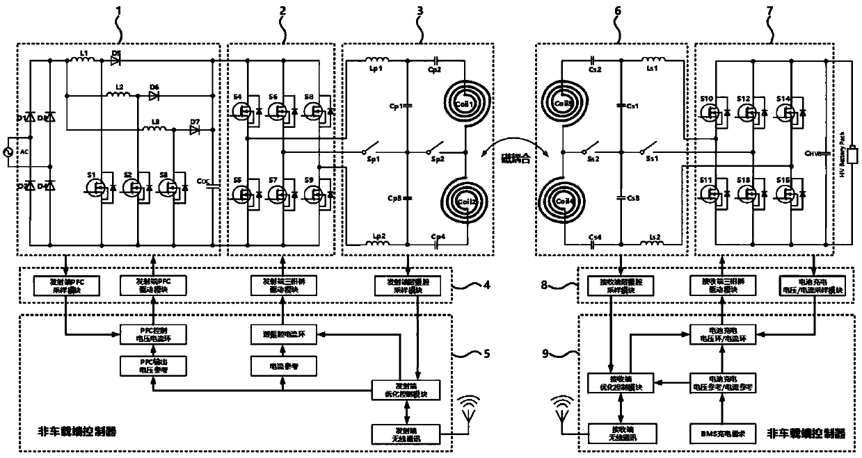
[0053] Please refer to figure 1 , which is a schematic diagram of the inductive wireless power transfer system in this embodiment. Such as figure 1 As shown, the inductive wireless power transfer system includes: a transmitting end part and a receiving end part, and the transmitting end part includes: a sequentially connected power factor correction module 1 (or PFC module), a three-phase bridge inverter at the transmitting end Module 2, transmitter resonant module 3, transmitter sampling / driving module 4 and transmitter control module 5, the transmitter sampling / drive module 4 is also connected with the power factor correction module 1 and the transmitter three-phase bridge respectively The inverter module 2 is connected; the receiving end part includes: a receiving end resonant module 6 connected in sequence, a receiving end three-phase bridge rectification module 7, a receiving end sampling / driving module 8 and a receiving end control module 9, and the receiving end sampli...
Embodiment 2
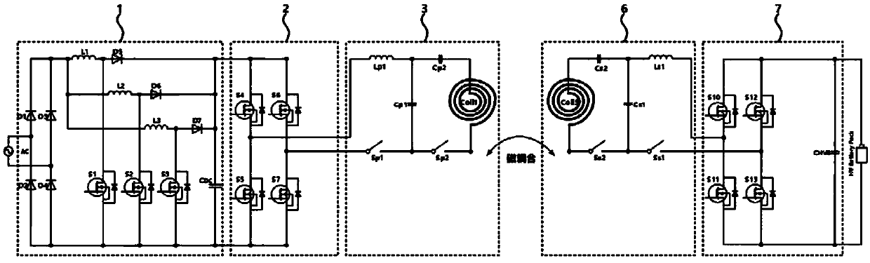
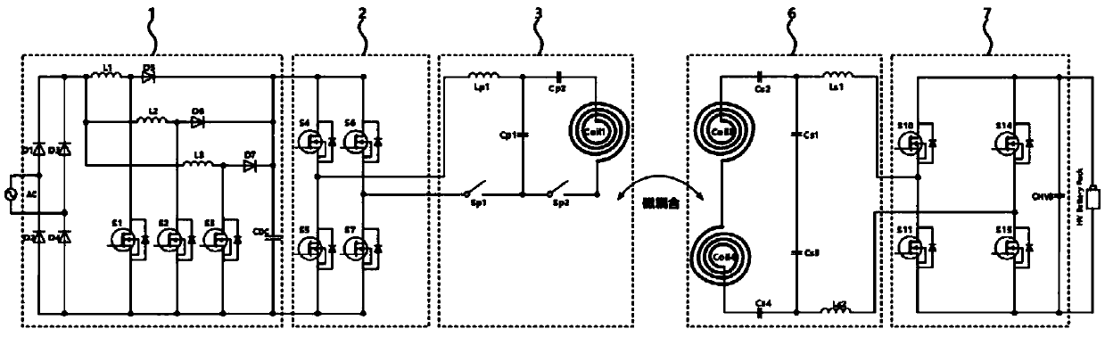
[0074] Please refer to Figure 7 , which is a schematic diagram of the application of the multi-adjustment parameter control method in the present invention. Such as Figure 7 As shown, the multi-adjustment parameter control method includes the following steps:
[0075] Adopt power factor correction voltage and current double closed-loop control power factor correction module 1;
[0076] All switches in the resonant module 3 at the transmitting end and the resonant module 6 at the receiving end are controlled on and off (ie, the first switch Sp1, the second switch Sp2, the first receiving switch Ss1, and the second receiving switch Ss2);
[0077] The three-phase bridge inverter module 2 at the transmitting end and the three-phase bridge rectifying module 7 at the receiving end are controlled by phase shifting.
[0078] There are five system power adjustment parameters that can be changed based on the multi-adjustment parameter control method, specifically including: PFC out...
PUM
 Abstract
Description
Claims
Application Information