Method for preparing nano-scale catalyst through ultrasonic atomization plasma reaction

A plasma and catalyst technology, which is used in the field of ion reaction to prepare nano-scale catalysts, can solve the problems of high temperature agglomeration of catalyst active components, and achieve the effects of high catalytic oxidation capacity, improved efficiency and high efficiency.

Inactive Publication Date: 2019-04-09
ZHEJIANG GONGSHANG UNIVERSITY
View PDF15 Cites 7 Cited by
  • Summary
  • Abstract
  • Description
  • Claims
  • Application Information

AI Technical Summary

Problems solved by technology

[0005] However, in the catalyst loaded with active components obtained by calcination or high-temperature reduction with hydrogen, the active components of the catalyst will agglomerate at high temperature

Method used


Image

  • Method for preparing nano-scale catalyst through ultrasonic atomization plasma reaction
  • Method for preparing nano-scale catalyst through ultrasonic atomization plasma reaction
  • Method for preparing nano-scale catalyst through ultrasonic atomization plasma reaction

Examples


Embodiment 1

[0047] Preparation of 5wt% Nanoscale Ag / Al by Ultrasonic Atomized Plasma Reaction 2 o 3 catalyst:

[0048] (1) Add 20 mL of 3.94% AgNO to the ultrasonic nebulizer 3 Solution, pass 200mL / min carrier gas nitrogen into the ultrasonic nebulizer, the gas is bubbled through the ultrasonic nebulizer, and the nebulized gas containing the reaction precursor is brought out; the nebulization rate is 10mL / h.

[0049] (2) The nano-scale aerosol gas containing the catalytic active ingredient flowing out from the ultrasonic atomizer is passed into the mixer and mixed evenly with supplementary nitrogen gas with a flow rate of 100mL / min.

[0050] (3) Continuously and slowly pass the nanoscale aerosol gas containing the catalyst active component through the Al containing 2g 1.6-2.0mm 2 o 3 The tubular dielectric barrier discharge reactor of small balls, the catalyst carrier small balls are arranged between two metal electrodes of the reactor. Turn on the switch of the tube electric furnace...

Embodiment 2

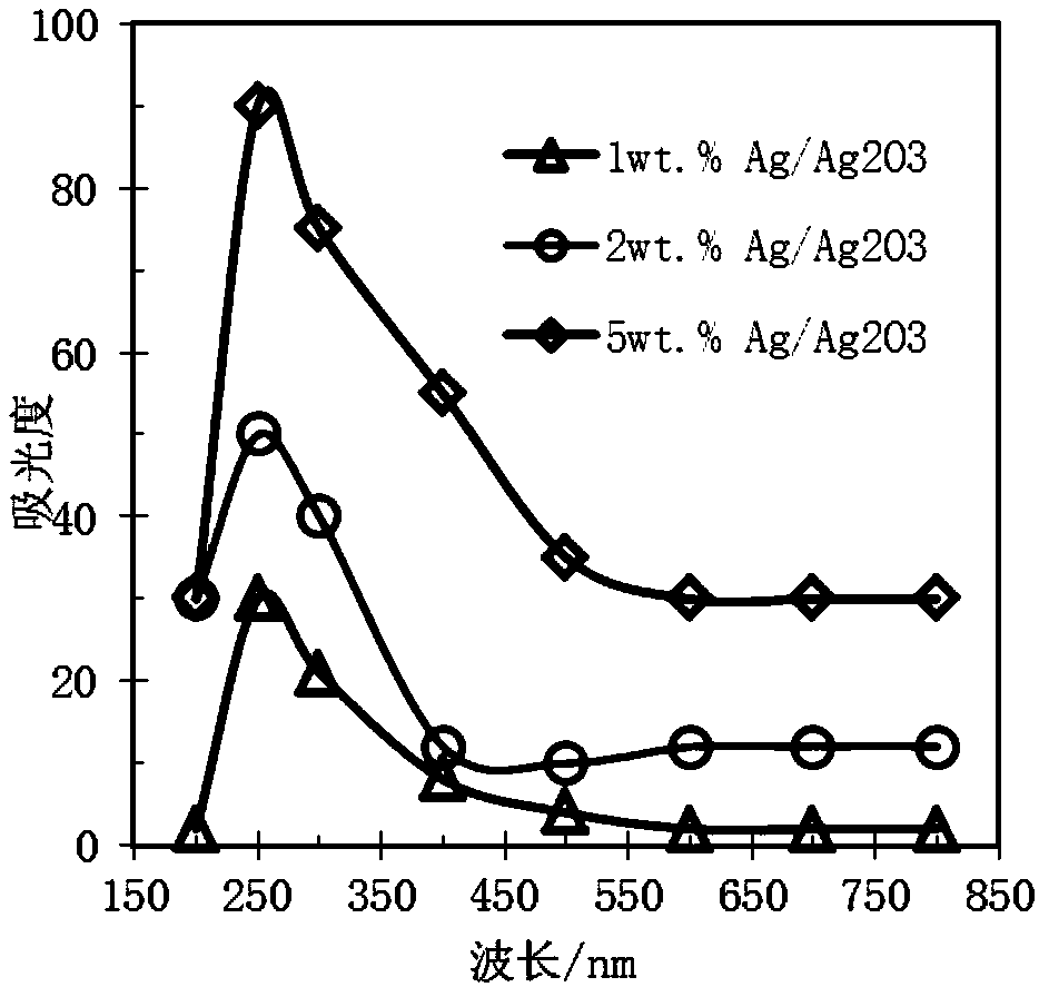
[0055] adjust AgNO 3 concentration of the solution, and ensure that Al 2 o 3 The amount of pellets, experimental temperature, discharge power, discharge time and other factors are the same, and Ag / Al with different loadings are prepared 2 o 3 Catalysts, Ag / Al with different loadings 2 o 3 The absorbance of the catalyst as a function of wavelength is shown in image 3 shown. It is known from experiments that Ag / Al 2 o 3 The absorbance of the catalysts reached the peak at a wavelength of about 250nm, and the catalytic performance of the catalyst with 5wt.% Ag loading was the best, followed by 2wt.% Ag loading, and 1wt.% Ag loading was the worst.

Embodiment 3

[0057] Precursor solution replaced with HAuCl 4 and H 2 PtCl 6 solution, adjust HAuCl 4 and H 2 PtCl 6 concentration of the solution, and ensure that Al 2 o 3 The amount of pellets, experimental temperature, discharge power, discharge time and other factors are the same, and Au / Al with different loadings are prepared 2 o 3 Catalysts and Pt / Al with different loadings 2 o 3 catalyst.


PUM

PropertyMeasurementUnit
diameteraaaaaaaaaa
diameteraaaaaaaaaa

Abstract

The invention discloses a method for preparing a nano-scale catalyst through ultrasonic atomization plasma reaction. The method comprises the following steps: (1) introducing an active component intoan ultrasonic atomizer, and introducing carrier gas into the ultrasonic atomizer for bubbling to bring out atomized gas containing active component precursor, so as to form aerosol; putting a catalystcarrier into a discharging gap of a plasma reactor, uniformly mixing aerosol flowing from the ultrasonic atomizer with supplemented carrier gas, enabling the mixture to continuously flow through thedischarging gap, heating gas in the plasma reactor, starting a high-voltage discharging device, continuously keeping atomization and high-voltage discharging states to reduce metal ions in active components of the aerosol into metal monomers loaded to the catalyst carrier. Compared with traditional methods, the catalyst prepared by virtue of the method has the advantages that the catalytic activity is high, the preparation cost of the catalyst is low, the preparation process is simple, and the catalyst has an extremely high industrial application value.

Description

technical field [0001] The invention relates to the technical field of designing industrial catalysts, in particular to a method for preparing nanoscale catalysts by means of ultrasonic atomization plasma reaction. Background technique [0002] In a chemical reaction, a substance that can change the chemical reaction rate (increase or decrease) of the reactants without changing the chemical balance, and whose quality and chemical properties have not changed before and after the chemical reaction is called a catalyst (a solid catalyst is also called a catalyst). According to statistics, more than 90% of industrial processes use catalysts, such as chemical, petrochemical, biochemical, and environmental protection. [0003] Catalysts loaded with active components can usually be obtained by dispersing the precursor of the active component of the catalyst on the surface of the carrier by impregnation, ion exchange, co-precipitation or deposition, followed by drying, calcining or ...

Claims


Application Information

Patent Timeline
Patent Type & Authority Applications(China)
IPC IPC(8): B01J37/34B01J23/50B01J23/42
CPCB01J23/42B01J23/50B01J37/34B01J37/343
Inventor 姚水良沈怡洁谢涵吴欣月
Owner ZHEJIANG GONGSHANG UNIVERSITY
Why Eureka
Try Eureka