Unmanned aerial vehicle line inspection control system based on video image processing
A technology of video image and control system, applied in control/adjustment system, vehicle position/route/altitude control, non-electric variable control and other directions, can solve the problems of signal difference and large error, reduce costs, solve signal difference, The effect of less disturbance from the external environment
- Summary
- Abstract
- Description
- Claims
- Application Information
AI Technical Summary
Problems solved by technology
Method used
Image
Examples
Embodiment 1
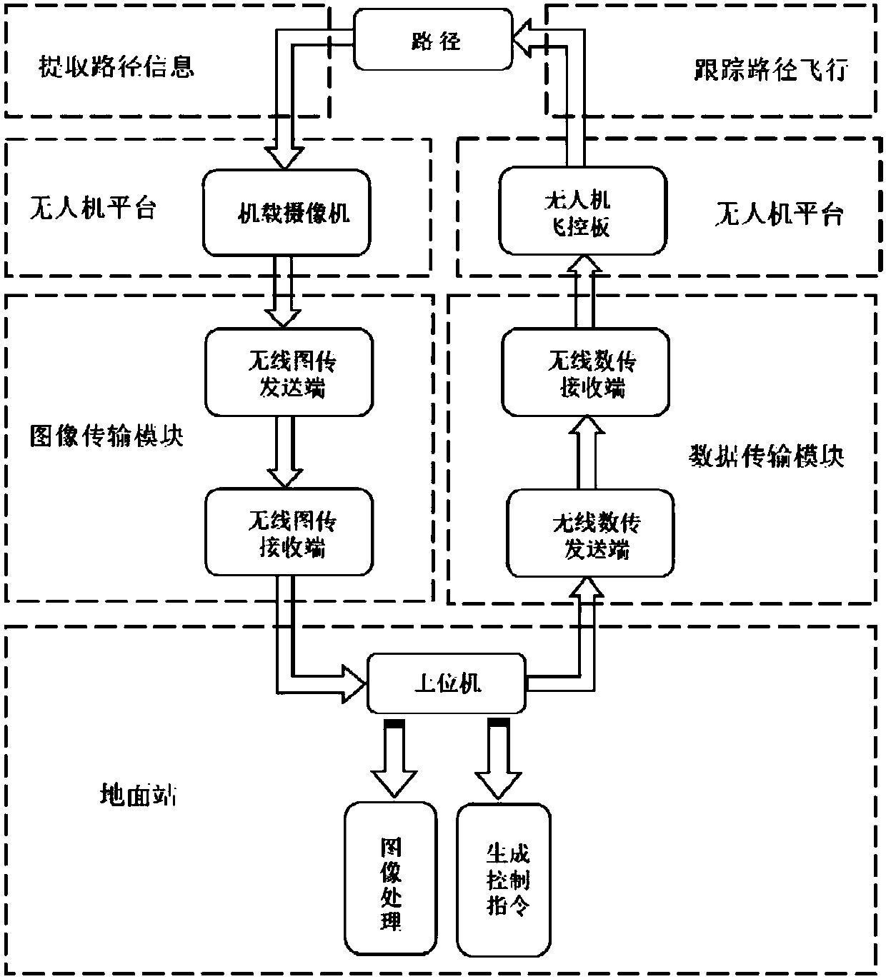
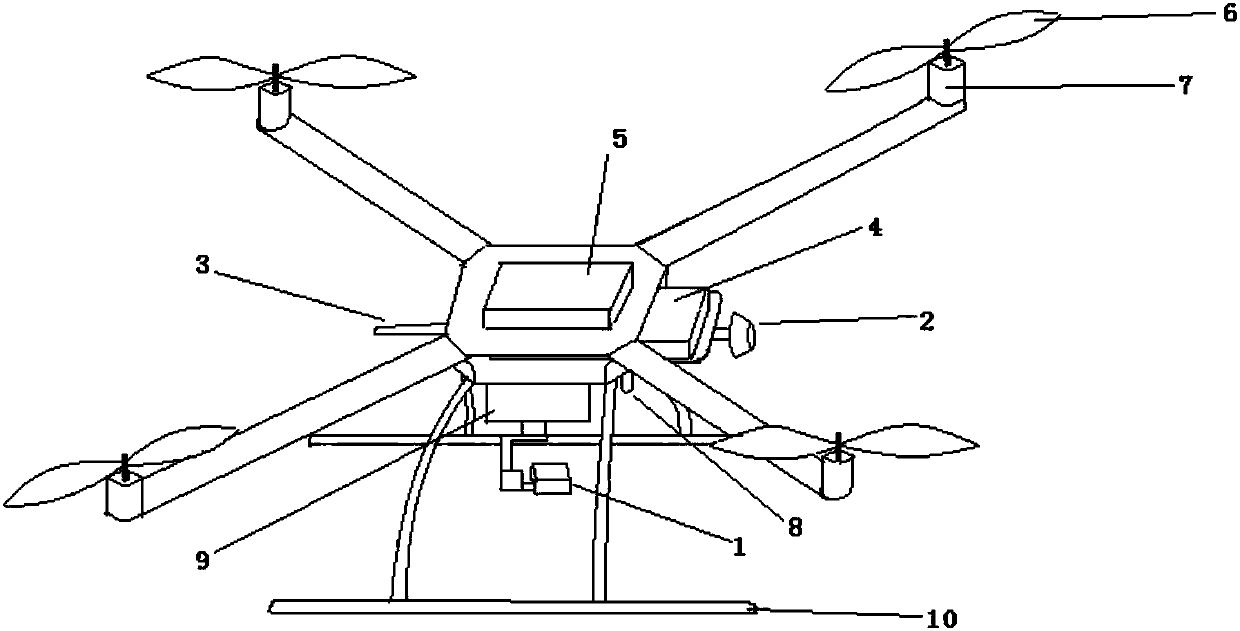
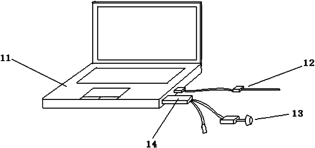
[0017] Vision-based quadrotor UAV path tracking system, which consists of a quadrotor UAV platform figure 2 , PC ground station image 3 , camera 1, PC 11, wireless image transmission equipment 2, wireless data transmission equipment 3 and other modules. Turn on the remote control, plug in the battery 4, press and hold the safety switch on the drone, wait until the switch indicator light is on, the drone is in standby mode, push the left joystick of the remote control to the lower right corner, unlock the drone, and push The left control stick controls the throttle and yaw to make the drone take off, push the right control stick of the remote control to control the roll and pitch of the drone, and place the drone above the target.
[0018] The camera 1 located on the four-rotor UAV platform 9 collects ground video images, extracts path information, and sends them to the wireless image transmission receiving device 13 in real time through the four-rotor UAV platform equipped ...
Embodiment 2
[0021] The drone can be set to automatically take off and land at a fixed height with one button, and it can also be used to take off manually. When one-button automatic take-off, when the drone enters the standby state, after the drone is unlocked by remote control, the control switch on the left side of the remote control can be toggled upwards, and a signal is sent to the drone through the remote control antenna, and the control program starts to automatically take off at a fixed height. Use Sonar 8 to determine the altitude, and set the flight altitude through the program. In this case, the left control stick only controls the yaw of the drone and cannot control the throttle. Use the right control stick to control the roll and pitch of the drone. After flying above the guide line, toggle the control switch on the right side of the remote control to start the automatic flight mode to realize automatic line inspection.
Embodiment 3
[0023] Vertical Movement: Vertical movement is relatively easy. exist Figure 4 Among them, because there are two pairs of motors that turn in opposite directions, their counter torque to the fuselage can be balanced. When the output power of the four motors is increased at the same time, the increase in the rotor speed will increase the total pulling force. When the total pulling force is enough to overcome the weight of the whole machine , the quadrotor aircraft will rise vertically from the ground; otherwise, the output power of the four motors will be reduced at the same time, and the quadrotor aircraft will descend vertically until it lands smoothly, realizing the vertical motion along the z-axis. When the external disturbance is zero and the lift generated by the rotor is equal to the weight of the aircraft, the aircraft will remain in a hovering state.
[0024] Pitch movement: in Figure 4 , the speed of motor 1 increases, the speed of motor 3 decreases, and the speed...
PUM
 Abstract
Description
Claims
Application Information
 - R&D
- Intellectual Property
- Life Sciences
- Materials
- Tech Scout
- Unparalleled Data Quality
- Higher Quality Content
- 60% Fewer Hallucinations
Browse by: Latest US Patents, China's latest patents, Technical Efficacy Thesaurus, Application Domain, Technology Topic, Popular Technical Reports.
© 2025 PatSnap. All rights reserved.Legal|Privacy policy|Modern Slavery Act Transparency Statement|Sitemap|About US| Contact US: help@patsnap.com


