Permanent magnet synchronous motor rotor location full-order sliding mode observation device and method

A technology of permanent magnet synchronous motor and full-order sliding mode, which is applied in the control of electromechanical transmission, control of generators, motor generator control, etc. Occupying DSP and other issues

Active Publication Date: 2019-04-09
ZHENGZHOU UNIV
View PDF3 Cites 6 Cited by
  • Summary
  • Abstract
  • Description
  • Claims
  • Application Information

AI Technical Summary

Problems solved by technology

[0004] The traditional sliding mode observer has the following problems: using the sign function as the switching function causes the system to have high-frequency chattering problems, and the back EMF signal also contains high-frequency harmonic components; the introduction of the low-pass filter will cause phase delay and thus A phase compensation module has to be added; when extracting the rotor position information, the arctangent function is used to calculate, and the look-up table method will occupy a large amount of DSP memory, and it is often difficult to achieve the expected accuracy
In view of the above problems, one of the existing chattering suppression methods is to directly replace the switching function with a conventional saturation function, so that the control between the boundary layers becomes continuous, but the sliding mode gain of this method is a fixed value , which makes the sliding mode gain applicable in the lo

Method used


Image

  • Permanent magnet synchronous motor rotor location full-order sliding mode observation device and method
  • Permanent magnet synchronous motor rotor location full-order sliding mode observation device and method
  • Permanent magnet synchronous motor rotor location full-order sliding mode observation device and method

Examples


Embodiment 1

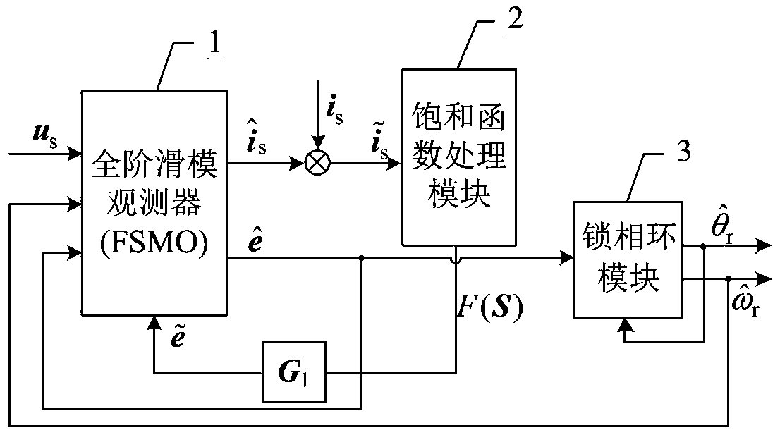
[0043] Such as figure 1 with figure 2 As shown, a permanent magnet synchronous motor rotor position full-order sliding mode observation device, the device includes a full-order sliding mode observer 1, a saturation function processing module 2 and a phase-locked loop module 3;

[0044] The full-order sliding mode observer 1 is provided with the stator voltage u in two-phase static coordinates s Input terminal, rotor speed observation value Observation error of back EMF in input terminal and two-phase stationary coordinate system input terminal;

[0045] The stator current observation value of the full-order sliding mode observer 1 Output terminal and stator current value i s After making a difference, the sliding mode function control vector F (S) under the permanent magnet synchronous motor two-phase stationary coordinate system is output through the saturation function processing module 2; the sliding mode function control vector F (S) is passed through the sliding ...

Embodiment 2

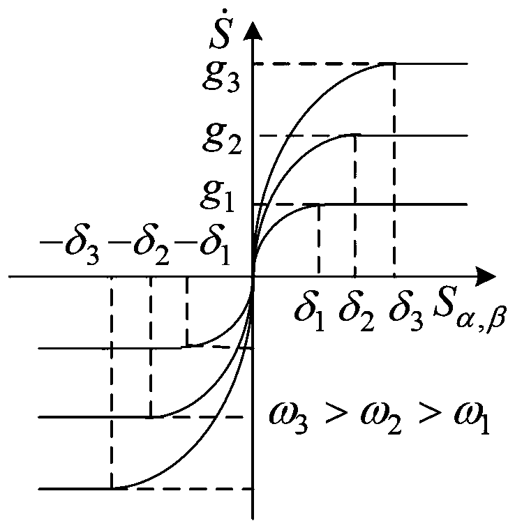
[0075] Combine below figure 2 This embodiment is described. This embodiment is a further description of the full-order sliding mode observation method for the rotor position of the permanent magnet synchronous motor described in the first embodiment. In step 3, the sliding mode function control vector F (S) is passed through the sliding mode gain matrix G 1 The rear boundary layer changes in the form of figure 2 As shown, the observation error of the back electromotive force in the two-phase stationary coordinate system The expression is

[0076]

Embodiment 3

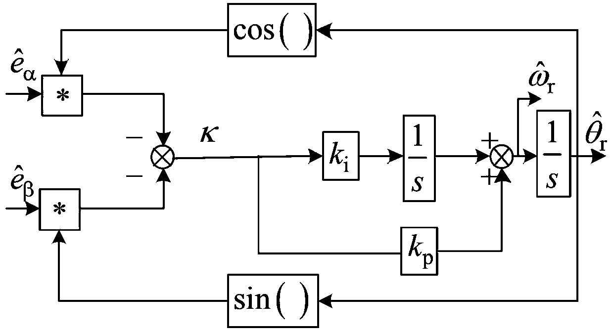
[0078] Combine below image 3 Describe this embodiment. This embodiment is a further description of the full-order sliding mode observation method for the rotor position of a permanent magnet synchronous motor described in Embodiment 1. The working principle of the phase-locked loop module in step 5 is as follows image 3 As shown, its working process is:

[0079] Step 51, Observing the rotor position of the permanent magnet synchronous motor After the cosine operation and the observed value of the α-axis back electromotive force multiplied, ie Observation of rotor position of permanent magnet synchronous motor After the sine operation and the observed value of the β-axis back electromotive force multiplied, ie

[0080] Step 52, for the obtained in step 51 with Perform heterodyne calculation to get the rotor position error signal κ of the permanent magnet synchronous motor after heterodyne processing

[0081]

[0082] Step 53: After the rotor position error ...


PUM


Abstract

The invention provides a permanent magnet synchronous motor rotor location full-order sliding mode observation device and method. The device comprises a full-order sliding mode observer, a saturationfunction processing module and a phase-locked loop module; in the method provided by the invention, an observation value as shown in description of the stator current can be output after the stator voltage us of the permanent magnet synchronous motor processed through a full-order sliding mode observer; the current error as shown in description is obtained after making the difference processing onthe value as shown in description and the stator current value is; a sliding mode function control vector F(S) is output after the value as shown in description processed through the saturation function processing module; the sliding mode function control vector F(S) in the saturation function processing module adopts a hyperbolic tangent function with adjustable boundary layer thickness, the adjusting of the boundary layer thickness is performed according to the rotating speed self-adaptive law of the switch gain gr, the counter electromotive force observation error as shown in description is obtained after the FS processed through a sliding mode gain matrix G1, the back counter observation value as shown in description is output after the value as shown in description processed througha full-order sliding mode observer; the value as shown in description is served as a state variable to be fed back to the full-order sliding mode observer to participate the update computation; a permanent magnet synchronous motor rotor location observation value as shown in description and the rotating speed observation value as shown in description are output after the value as shown in description is processed through the phase-locked loop module.

Description

technical field [0001] The invention belongs to the field of motor control, and in particular relates to a full-order sliding mode observation device and method for the rotor position of a permanent magnet synchronous motor. Background technique [0002] In high-performance applications, mechanical sensors such as incremental photoelectric encoders, magnetic encoders, resolvers, and Hall position sensors are widely used to detect rotor information. These mechanical sensors can detect the rotor position and rotational speed of the rotor's rotating state, but it is difficult to detect the initial position of the rotor or need to be replaced with a more complete and more expensive detection device. In addition, the mechanical sensor requires a large number of leads, which reduces the reliability of the system, thereby limiting the application of permanent magnet synchronous motors in some special occasions. Especially in some harsh environments, such as mechanical sensors unde...

Claims


Application Information

Patent Timeline
IPC IPC(8): H02P21/00H02P21/14H02P21/13H02P21/18H02P21/24
CPCH02P21/0007H02P21/13H02P21/14H02P21/18H02P21/24
Inventor 王要强冯玉涛朱亚昌李明辉林万里海德伦陈根永董亮辉李忠文齐歌韩云飞孙世伟
Owner ZHENGZHOU UNIV
Why Eureka
Try Eureka