Dynamic clean maintenance system and method for high power terminal optical system

An optical system and high-power technology, applied in the direction of cleaning methods using gas flow, chemical instruments and methods, cleaning methods and appliances, etc., can solve the problem of not being able to effectively guarantee the cleanliness of the terminal optical components and even the terminal cavity, and the surface of the optical components Issues not effectively addressed, limiting drive load capacity and high throughput operation

Active Publication Date: 2019-04-16
LASER FUSION RES CENT CHINA ACAD OF ENG PHYSICS
View PDF10 Cites 4 Cited by
  • Summary
  • Abstract
  • Description
  • Claims
  • Application Information

AI Technical Summary

Problems solved by technology

The terminal optical system of the National Ignition Facility in the United States and a large-scale laser device in China have adopted the small-volume gas replacement technology in the atmosphere chamber environment. The long-term operation results show that the cleanliness of the surface of the optical components has not been effectively solved, and deposits in the terminal optical system A large number of dust and aerosol pollutants generated after the damage of optical components lead to rapid contamination of clean optical components after they are put on the shelf, and the life of optical components is greatly shortened. This has become a bottleneck that limits the load capacity and high-throughput operation of the drive.
[0004] To sum up, the cleanliness of the terminal optical system of high-power laser devices is the main factor limiting the load capacity of the terminal optical components, and the existing cleaning control methods cannot effectively guarantee the cleanliness of the terminal optical components and even the terminal cavity, which greatly The improvement of the output capability of high-power laser devices is limited. Therefore, an effective cleaning and purging method for the terminal optical system is required to improve the load capacity of the terminal optical components

Method used


Image

  • Dynamic clean maintenance system and method for high power terminal optical system
  • Dynamic clean maintenance system and method for high power terminal optical system

Examples


Embodiment 1

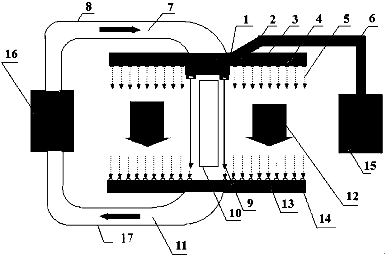
[0030] Such as figure 1 Shown is a schematic diagram of a dynamic cleanliness maintenance system for a high-power terminal optical system, wherein the optical element (10) in the single-beam terminal optical system is a frequency-doubled crystal element, and the optical element (10) is located in the terminal optical Inside the cavity of the system, between the fundamental frequency window and the frequency tripler crystal, the element size is 430mm. In practical applications, due to laser ablation during laser targeting, a large amount of high-speed moving dust and aerosol pollutants will be formed in the cavity of the terminal optical system. A vortex will form nearby, causing dust and aerosol pollutants to fail to get out of the cavity in time, and there is even a danger of adhering to the surface of the optical element.

[0031] In order to improve the use environment of the optical element (10), it will be processed by the system for maintaining dynamic cleanliness of th...

Embodiment 2

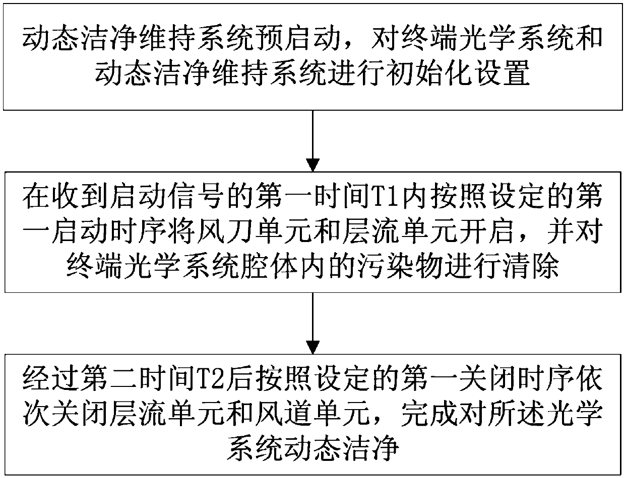
[0042] This embodiment is a method for maintaining dynamic cleanliness of high-power terminal optical systems. The method is implemented based on any of the aforementioned dynamic cleanliness maintenance systems for terminal optical systems, such as figure 2 As shown, the specific implementation steps of the method are as follows:

[0043] Step S1, the dynamic cleanliness maintenance system is pre-started, the terminal optical system and the dynamic cleanliness maintenance system are initialized, and the laminar flow unit is opened in a small cycle according to the set pre-startup operation;

[0044] According to the 430mm caliber of the optical element and the limitation of the use angle, the size of the pollutants to be cleaned and purged is on the order of microns, and the optical design of the coupled terminal system, it is determined that the distance between the double frequency crystal and the front and rear elements must not be less than 100mm. At the same time, in or...


PUM


Abstract

The invention discloses a dynamic clean maintenance system and method for a high power terminal optical system, and belongs to the technical research field of high power laser devices. The system comprises a laminar flow unit and a wind knife unit, the laminar flow unit is used for providing dynamic clean laminar flow, and the wind knife unit is used for providing a high pressure air knife air curtain. During the long-term operation of the high power terminal optical system, the life of optical elements is greatly shortened due to the fact that dust and aerosol pollutants produced by targetingare deposited on the surface of the internal optical elements in the high power terminal optical system, and the clean control of the terminal optical elements becomes a bottleneck of limiting the high throughput operation of the device; therefore, a technical measure for realizing the surface clean control of the optical elements by coupling the wind knife air curtain protection and the clean laminar flow protection is provided, the dust and aerosol pollutants produced by targeting can be prevented from being attached to the surfaces of the optical elements and are discharged out of the terminal optical system in time, so that the surface cleanliness of the optical elements in the terminal optical system is maintained for a long time.

Description

technical field [0001] The invention relates to the technical research field of high-power laser devices, and specifically relates to a dynamic cleaning maintenance system and method for cleaning and purging optical elements in high-power terminal optical systems. Background technique [0002] In high-power laser devices, the load capacity of optical components is one of the determining factors for the output capacity of the device, and the cleanliness of optical components directly affects the load capacity of optical components. Research has found that optical components will produce a large amount of dust and aerosol pollutants under laser irradiation conditions, especially when the optical components have surface damage, the pollutants will increase in multiples; once micron-sized pollutants adhere to the surface of optical components, It is extremely difficult to remove by airflow blowing. On the other hand, the terminal optical system has a variety of placement method...

Claims


Application Information

Patent Timeline
Patent Type & Authority Applications(China)
IPC IPC(8): B08B17/02B08B5/02B08B13/00
CPCB08B5/02B08B13/00B08B17/02
Inventor 冯斌李平卢礼华朱德燕柴向旭王礼权王冠中敬域堃郑奎兴朱启华
Owner LASER FUSION RES CENT CHINA ACAD OF ENG PHYSICS
Why Eureka
Try Eureka