Integrated sewage treatment equipment

A technology of sewage treatment equipment and aeration equipment, applied in the field of water pollution control, can solve the problems of prolonging the backwashing time of membrane modules, low sewage treatment efficiency, and large operating load, so as to reduce sludge disposal costs and reduce fouling Chance, the effect of reducing the operating load

Inactive Publication Date: 2019-04-23
重庆尚泽源环保科技有限公司
View PDF8 Cites 10 Cited by
  • Summary
  • Abstract
  • Description
  • Claims
  • Application Information

AI Technical Summary

Problems solved by technology

[0004] Aiming at the deficiencies in the prior art, the present invention provides an integrated sewage treatment equipment, which solves the problems in the prior art that the sewage treatment efficiency is not high, the operating load of the membrane module is large and the fouling is easy due to the separation of mud and water. , prolong the backwashing time of the membrane module

Method used


Image

  • Integrated sewage treatment equipment
  • Integrated sewage treatment equipment
  • Integrated sewage treatment equipment

Examples


Embodiment 1

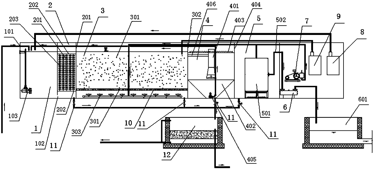
[0043] Such as figure 1 As shown, the integrated sewage treatment equipment includes anoxic pool 1, anaerobic pool 2, aerobic pool 3, sedimentation pool 4, and membrane reaction pool 5 connected sequentially from front to back. Anoxic pool 1 is provided with a water inlet 101 , the aerobic pool 3 is provided with an overflow port 302, the anoxic pool 1 is connected to the anaerobic pool 2 through the first water outlet 102 located at its lower part, and the anaerobic pool 2 is connected through the second water outlet 201 located at its upper part The oxygen tank 3 is provided with a connecting pipe 406 on the overflow port 302, and a central cylinder 401 is provided in the sedimentation tank 4, and the connecting pipe 406 is connected to the central cylinder 401, so the sedimentation tank 4 is connected to the aerobic tank 3 through the overflow port 302.

[0044] The anoxic pool 1 is provided with a stirrer 103 , and the anoxic pool 1 is connected to a carbon source dosing d...

Embodiment 2

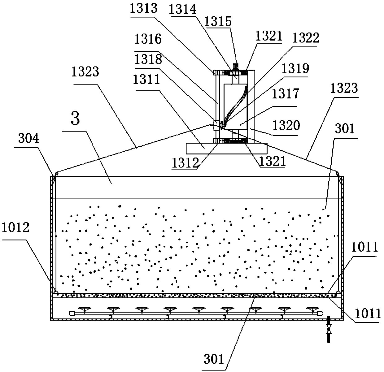
[0054] see Figure 2-5 , on the basis of Embodiment 1, this embodiment adds the following features:

[0055] It also includes a lifting device 13 located above the aerobic pool 3. The lifting device 13 includes a placement table 1311, a bottom plate 1312, a top plate 1313, a circular shaft 1314, a motor 1315, a slide bar 1316, a drum 1317, a slider 1318, a guide The column 1319, the placing table 1311 is set above the aerobic pool 3 through the base height higher than the aerobic pool 3, the bottom plate 1312 is arranged on the top of the placing table 1311, the top plate 1313 is connected to the placing table 1311 through the support rod 1320, and The top plate 1313 is located above the bottom plate 1312, the bottom plate 1312 and the top plate 1313 are embedded with bearings 1321, one end of the circular shaft 1314 is inserted into the bearing 1321 in the bottom plate 1312, and the other end passes through the bearing 1321 in the top plate 1313 upwards and then penetrates th...


PUM


Abstract

The invention provides integrated sewage treatment equipment, which comprises an anoxic tank, an anaerobic tank, an aerobic tank, a sedimentation tank and a membrane reaction tank communicated sequentially from front to back, wherein an MBR membrane is arranged in the membrane reaction tank and communicated with an ultraviolet disinfector; aeration equipment is communicated with both the aerobic tank and the MBR membrane; an elastic filler is uniformly distributed in the anaerobic tank and an MBBR filler is arranged in the aerobic tank; a mixer is arranged in the anoxic pool, a carbon source adding device is communicated with the anoxic pool, and a medicine dosing barrel is communicated with the aerobic tank. Compared with the traditional sewage treatment device, the continuous aeration ofthe integrated sewage treatment equipment enables a moving bed in a flowing state and react more fully with the sewage, which greatly improves the treatment efficiency. The sedimentation tank is designed in front of the membrane reaction tank to separate the mud and water and remove the floating sludge, so that most of the mud is precipitated before entering the membrane area, thereby reducing the operating load of the MBR membrane, reducing the probability of fouling, delaying the service life of the membrane, also prolonging the backwashing cycle of the membrane and further ensuring the quality of the effluent.

Description

technical field [0001] The invention relates to the field of water pollution control, and specifically relates to integrated sewage treatment equipment. Background technique [0002] In the field of water pollution control, the existing main processes mainly include AO, AAO, oxidation ditch, MBR, MBBR, SBR and various variant processes of SBR. The MBBR process is to increase the biomass and biological species in the reactor by adding a certain amount of suspension carrier (MBBR filler) to the reactor, thereby improving the treatment efficiency of the reactor. Since the packing density is close to that of water, it is completely mixed with water during aeration, and the environment for microbial growth is gas, liquid and solid. The collision and shearing action of the carrier in the water makes the air bubbles finer and increases the utilization rate of oxygen. In addition, each carrier has different types of organisms inside and outside, some anaerobic or facultative bacte...

Claims


Application Information

Patent Timeline
Patent Type & Authority Applications(China)
IPC IPC(8): C02F9/14
CPCC02F9/00C02F1/44C02F1/32C02F2001/007C02F3/30C02F2303/04
Inventor 贺亚玲曹灿辉谢朝丽侯科源涂家辉李海瑞
Owner 重庆尚泽源环保科技有限公司
Why Eureka
Try Eureka