
Exhaust gas treatment method and system in polysilicon production process

A production process and exhaust gas treatment technology, applied in separation methods, chemical instruments and methods, vapor condensation, etc., can solve the problems of low efficiency, increased equipment investment, and high investment

Active Publication Date: 2019-04-26
XINTE ENERGY
View PDF10 Cites 1 Cited by
  • Summary
  • Abstract
  • Description
  • Claims
  • Application Information

AI Technical Summary

Problems solved by technology

[0004] 1. High energy consumption and high cost: At present, the condensation part of the tail gas recovery process requires a large amount of cooling capacity to condense the high-temperature tail gas, and a large amount of heat is required to heat and analyze hydrogen chloride in the absorption and analysis part
The heat and cold here consume a lot of steam and electricity. A 10,000-ton polysilicon tail gas recovery process requires hundreds of thousands of yuan in steam and electricity costs every day, resulting in high production costs for polysilicon.
[0005] 2. Low efficiency and high investment: the existing tail gas recovery process can satisfy the separation and purification of hydrogen and hydrogen chloride, but trichlorosilane, silicon tetrachloride, and dichlorodihydrosilane are basically not separated and are still sent to To the purification process, separation and purification are carried out again in the rectification tower, and the separation efficiency of the tail gas recovery process is low
The re-separation of chlorosilanes in the purification process not only increases the separation steps and energy consumption, but also increases the equipment investment

Method used


Image

  • Exhaust gas treatment method and system in polysilicon production process

Examples


Embodiment 1

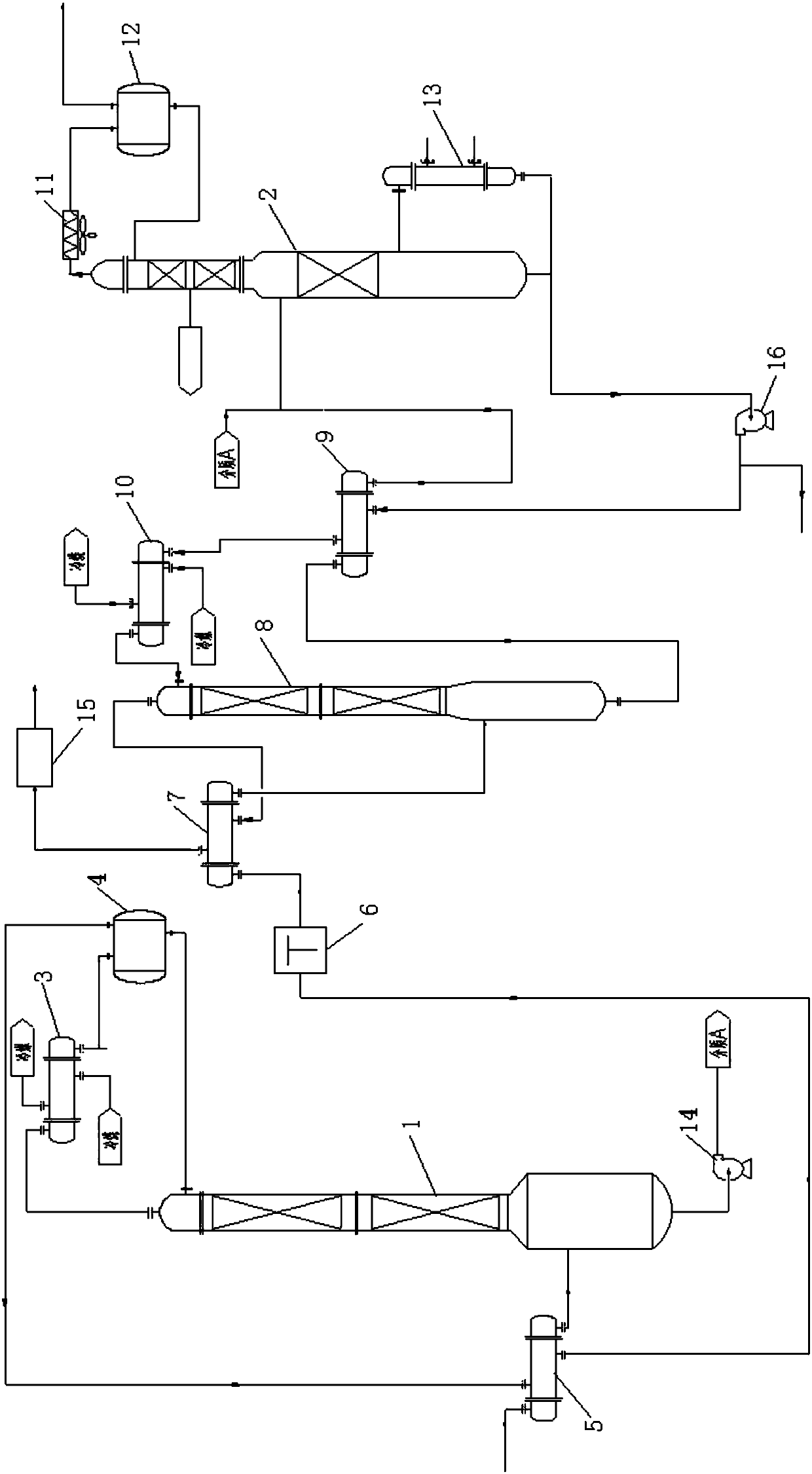
[0067] This embodiment provides a tail gas treatment system in the polysilicon production process, including:

[0068] The tail gas cooling tower is used to cool, liquefy and separate the tail gas in the polysilicon production process to obtain the bottom liquid of the tail gas cooling tower.

[0069]The separation tower is connected to the tower bottom of the tail gas cooling tower, and is used to pass the tower bottom liquid of the tail gas cooling tower into the separation tower for rectification and purification, and collect the top gas at the top of the separation tower. The top gas includes hydrogen, Hydrogen chloride; the side line production liquid is produced at the top side line of the separation tower or the upper part of the separation tower, and the side line production liquid includes trichlorosilane and dichlorodihydrosilane; the bottom liquid of the separation tower is collected at the bottom of the separation tower , the bottom liquid of the separation tower i...

Embodiment 2

[0079] This embodiment provides a tail gas treatment method in the polysilicon production process using the tail gas treatment system in the polysilicon production process in the above-mentioned embodiment 1. The difference from the method in embodiment 1 is:

[0080] In this embodiment, the number of theoretical plates of the separation tower is 90 to 160, and the reflux ratio of the separation tower is 10, and the feed position entering the separation tower is the 50th to 80th theoretical plate downwards from the top of the separation tower. In the side line of the separation tower, the position of the side line production liquid is the first theoretical plate downward from the top of the separation tower.

[0081] In the present embodiment, the mol ratio of trichlorosilane in the side draw liquid of the separation tower is 95mol%; the tower still liquid of the separation tower contains trichlorosilane, wherein, the content of silicon tetrachloride The molar ratio is 90 mol%...

Embodiment 3

[0084] This embodiment provides a tail gas treatment method in the polysilicon production process using the tail gas treatment system in the polysilicon production process in the above-mentioned embodiment 1. The difference from the method in embodiment 1 is:

[0085] In this embodiment, the number of theoretical plates of the separation tower is 90 to 160, and the reflux ratio of the separation tower is 7, and the feed position entering the separation tower is the 50th to 80th theoretical plate downwards from the top of the separation tower. In the side line of the separation tower, the position of the side line production liquid is the 35th theoretical plate downward from the top of the separation tower.

[0086] In the present embodiment, the mol ratio of trichlorosilane in the side stream production liquid of the separation tower is 90mol%; The molar ratio is 95 mol%.

[0087] In this embodiment, the pressure at the top of the separation tower is 0.3Mpa, the temperature a...


PUM


Abstract

The invention discloses an exhaust gas treatment method and system in the polysilicon production process. The exhaust gas treatment method comprises the following steps: (1) exhaust gas is subjected to cooling liquefaction separation through an exhaust gas cooling tower, tower bottom liquid of the exhaust gas cooling tower is obtained in a tower bottom of the exhaust gas cooling tower, and a primary mixture comprises the tower bottom liquid of the exhaust gas cooling tower; and (2) the primary mixture is introduced into a separation tower to be fed for distillation purification, overhead gas is collected at the tower top of the separation tower and comprises hydrogen and hydrogen chloride, beside collection liquid is collected on the lateral line or the upper part of the tower top of the separation tower and comprises trichlorosilane and dichlorosilane, and tower bottom liquid of the separation tower is collected and comprises silicon tetrachloride. Hydrogen, hydrogen chloride, dichlorosilane, trichlorosilane and silicon tetrachloride in the tower bottom liquid of the exhaust gas cooling tower are separated, the separated components are not homologous compounds, the obtained mixtures have different proportioning requirements, and the downstream process requirements can be met.

Description

technical field [0001] The invention belongs to the technical field of polysilicon production, and in particular relates to a tail gas treatment method and system in the polysilicon production process. Background technique [0002] In the process of producing polysilicon by the improved Siemens method, the main function of the tail gas recovery process in the polysilicon production process is to recover the hydrogen, hydrogen chloride, dichlorodihydrosilane, trichlorosilane and silicon tetrachloride in the tail gas in the polysilicon production process. The principle of separation is as follows: firstly, according to the different boiling points of each component, the temperature of the tail gas is lowered several times. Chlorosilane has a high boiling point and is easy to be condensed. Under certain temperature conditions, chlorosilane is first condensed into liquid, while hydrogen and atmospheric Part of hydrogen chloride still exists in the gas phase, which realizes the p...

Claims


Application Information

Patent Timeline
Patent Type & Authority Applications(China)
IPC IPC(8): C01B33/035B01D5/00B01D53/00B01D53/14B01D53/18
CPCB01D5/00B01D5/0054B01D5/006B01D53/002B01D53/1456B01D53/18C01B33/035
Inventor 张伟王惠宋高杰陈朝霞相文强赵阳董越杰王强
Owner XINTE ENERGY
Learn More