Biomass gas coupled coal-fired unit power generation device

A technology for coal-fired units and power generation devices, applied in the gasification of granular/powdered fuels, the manufacture of combustible gases, and the petroleum industry, etc., which can solve the problems of low catalyst effective working temperature, denitrification that cannot be put into use, and low smoke temperature at the SCR inlet. , to achieve the effects of promoting stable combustion, increasing power generation time, and increasing inlet smoke temperature

Pending Publication Date: 2019-05-03
HARBIN BOILER
View PDF0 Cites 1 Cited by
  • Summary
  • Abstract
  • Description
  • Claims
  • Application Information

AI Technical Summary

Problems solved by technology

[0005] The purpose of the present invention is to solve the above-mentioned problems in the prior art, and further provide a biomass gasification coupled coal-fired unit power generation device, which solves the problem of low smoke temperature at the SCR inlet under ultra-low load conditions, which is lower than the effective working temperature of the catalyst , the problem that denitrification cannot be put into use; at the same time, it better realizes the coupled power generation of biomass gas and coal-fired units under the ultra-low load operation condition of coal-fired units, and avoids the impact of biomass gas mixed in the combustion zone under ultra-low load. Combustion of Coal Boiler and Influence of Performance Parameters

Method used


Image

  • Biomass gas coupled coal-fired unit power generation device
  • Biomass gas coupled coal-fired unit power generation device

Examples


Embodiment Construction

[0017] The present invention will be described in further detail below in conjunction with the accompanying drawings: the present embodiment is implemented on the premise of the technical solution of the present invention, and detailed implementation is provided, but the protection scope of the present invention is not limited to the following embodiments.

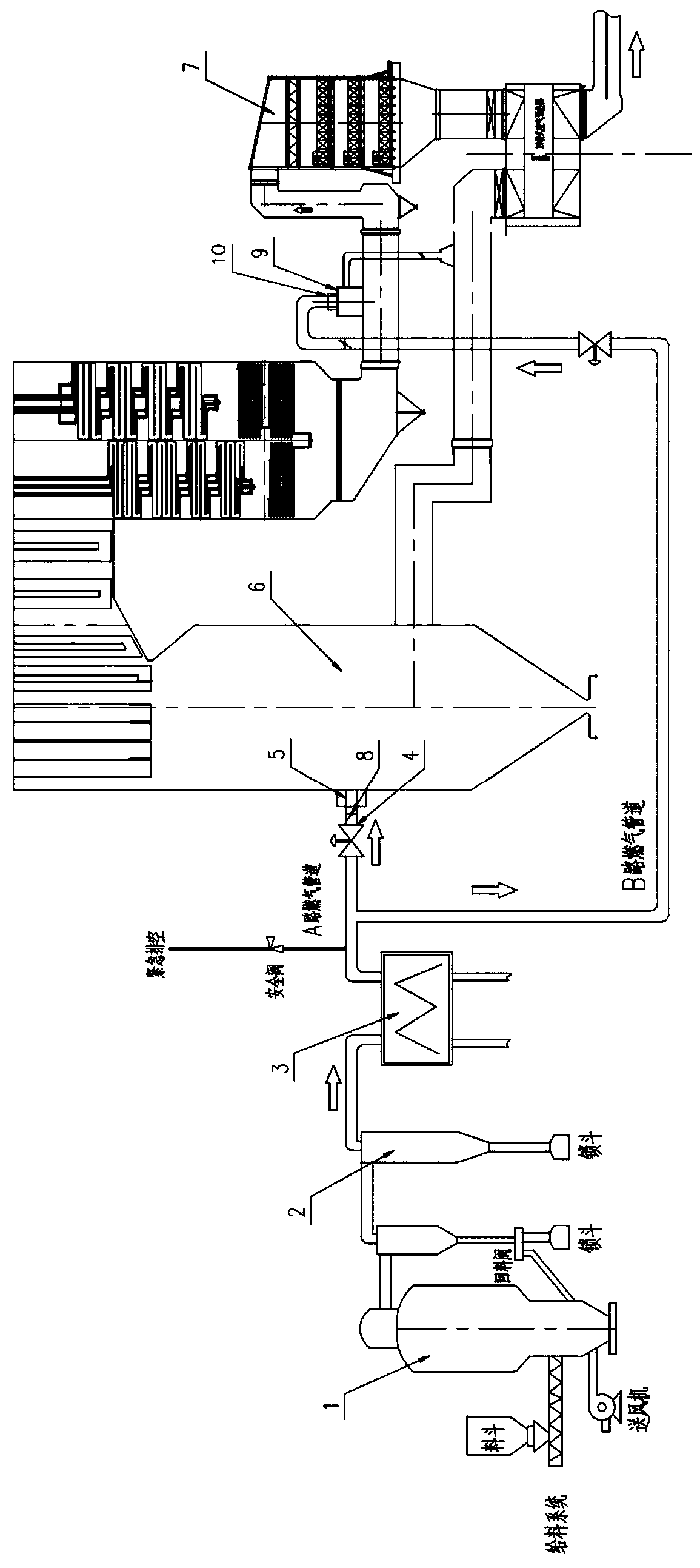
[0018] Such as figure 1 As shown, a biomass gasification coupling coal-fired unit power generation device involved in this embodiment includes a circulating fluidized bed gasifier 1, a cyclone dust collector 2, a gas heat exchanger 3, a valve 4, and a gas burner A5 , coal-fired boiler 6, SCR denitrification device 7, baffle plate 8, gas combustion chamber 9, gas burner B10, characterized in that the circulating fluidized bed gasifier 1, cyclone dust collector 2, gas heat exchanger 3 are connected sequentially through pipelines. One of the outlets of the gas heat exchanger 3 is connected to the furnace of the coal-fired boi...


PUM


Abstract

The invention provides a biomass gas coupled coal-fired unit power generation device, which mainly solves the problems that under an ultralow load situation, SCR inlet temperature is lower than effective working temperature of a catalyst, which causes that denitration cannot be put in use. A circulating fluidized bed gasifier, a cyclone dust collector, a fuel gas heat exchanger are successively connected via pipelines. The outlet of the fuel gas heat exchanger is divided into two paths: one passes through a fuel gas combustor A via a path-A fuel gas pipeline and is connected to the hearth of aboiler furnace, the other passes through a fuel gas combustor B via a path-B fuel gas pipeline and is connected to a horizontal flue in the front of a SCR denitration device. The SCR denitration device is connected to the outlet of a coal-firing boiler economizer through the horizontal flue. The fuel gas combustion chamber of the fuel gas combustor B is connected to a tail secondary air duct of the coal-firing boiler. The tail secondary air duct of the coal-firing boiler and the outlet flue of the SCR denitration device are respectively to a revolving air preheater. The device achieves coupled power generation of the biomass flue gas and the coal-fired unit under an ultralow load situation of the coal-fired unit.

Description

technical field [0001] The invention relates to the field of coal-fired boiler systems for power generation, in particular to a biomass gasification coupled coal-fired unit power generation device. Background technique [0002] With the continuous development of biomass power generation technology, "biomass gasification coupled coal-fired unit power generation technology" has become the mainstream technical route of biomass power generation due to its significant advantages of high biomass energy conversion rate and easy measurement. The biomass is converted into biomass gas after being gasified by the gasifier, and then the biomass gas is transported to the coal-fired boiler for combustion and power generation. [0003] On the one hand, due to the complexity of the biomass gasification system, when the coal-fired boiler needs variable load operation, the biomass gas cannot realize the flexible start and stop or fuel quantity adjustment similar to the coal mill, and when the...

Claims


Application Information

Patent Timeline
Patent Type & Authority Applications(China)
IPC IPC(8): C10J3/56C10J3/84C10J3/72
CPCY02P20/129
Inventor 于强徐彦辉韩升利于景泽殷亚宁佟力
Owner HARBIN BOILER
Why Eureka
Try Eureka