
A dual-frequency common-aperture waveguide slot antenna

A waveguide slot antenna, common aperture technology, applied in the field of antenna arrays, can solve the problems of low structural strength, interlayer separation, difficult processing, etc., to meet the scanning spacing requirements, good thermal conductivity, and reduce production costs.

Active Publication Date: 2020-07-24
CHINA ELECTRONIC TECH GRP CORP NO 38 RES INST
View PDF9 Cites 0 Cited by
  • Summary
  • Abstract
  • Description
  • Claims
  • Application Information

AI Technical Summary

Problems solved by technology

[0008] In order to solve the dual-band scanning working environment in the prior art, the conventional rectangular waveguide slot antenna cannot realize scanning due to size limitations, and the conventional microstrip antenna has a complex structure and is difficult to process; easy to deform and detach between layers; poor thermal conductivity; processing To solve the problem of low structural strength after the antenna array is formed, the present invention provides a dual-frequency common-aperture waveguide slot antenna

Method used


Image

  • A dual-frequency common-aperture waveguide slot antenna
  • A dual-frequency common-aperture waveguide slot antenna
  • A dual-frequency common-aperture waveguide slot antenna

Examples


Embodiment 1

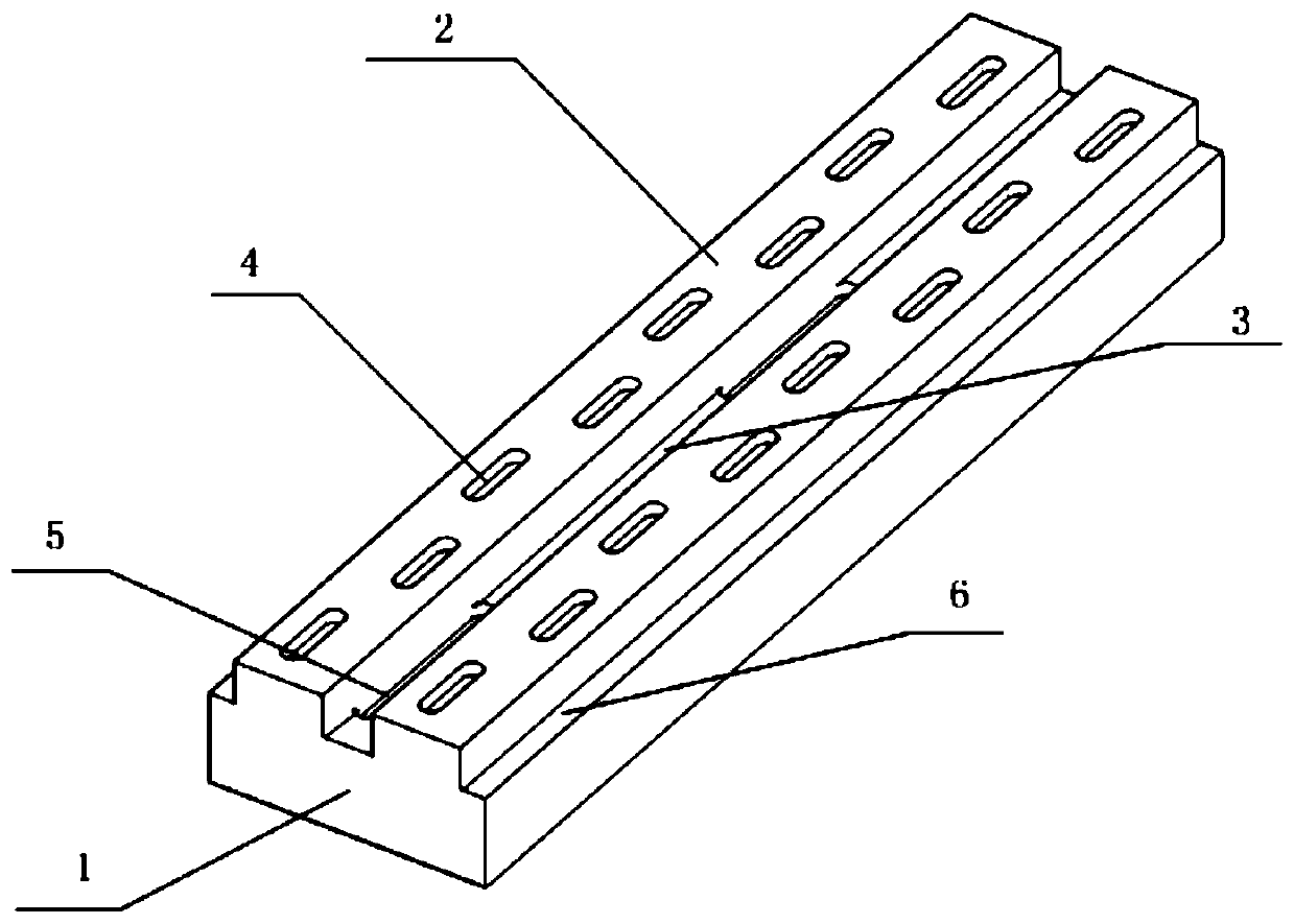
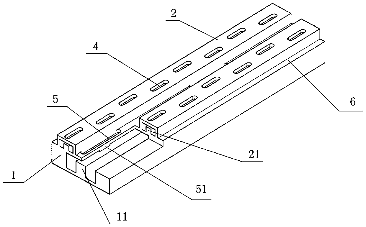
[0043] See figure 1 with figure 2 , A dual-frequency common-aperture waveguide slot antenna includes a metal waveguide 1. The cross section of the metal waveguide 1 is rectangular, and two parallel shoulder arms 2 are provided on the top. There is a groove 3 between the two shoulder arms 2. The outer sides of the two shoulder arms 2 corresponding to the length of the metal waveguide 1 are both For the choke groove 6. The cross-sectional width of the metal waveguide 1 is 0.7λ 1 ×The section height is 0.37λ 1 , Λ 1 Is the low-frequency center frequency wave; the low-frequency center frequency wavelength λ 1 It is 18.75mm. The working frequency of the low frequency band is 15.8~16.2Ghz.

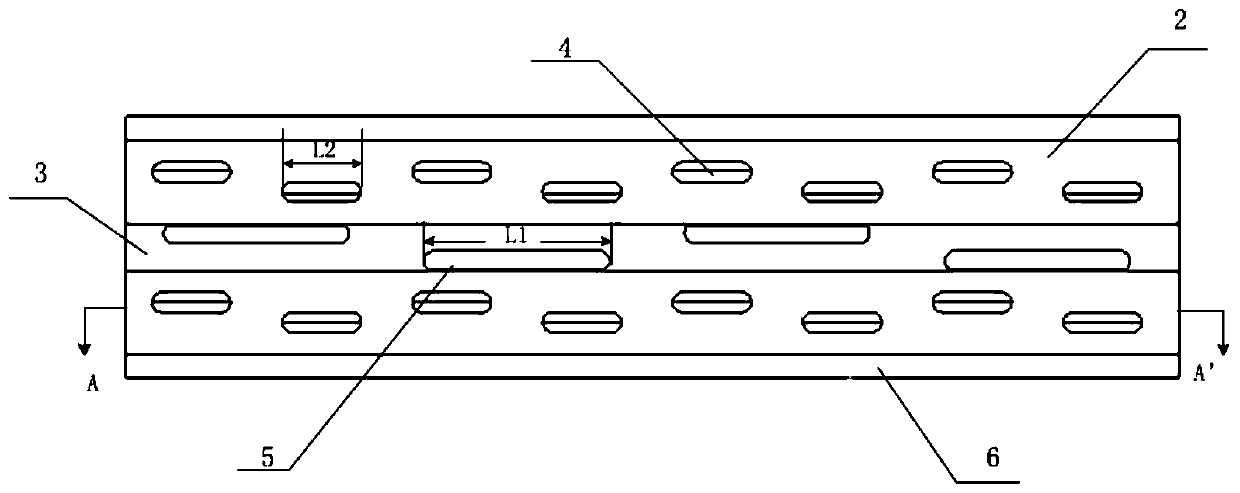
[0044] See figure 2 , Each shoulder arm 2 corresponding to the length of the metal waveguide 1 is provided with a high-frequency ridge waveguide 21, and high-frequency straight slits 4 are arranged on both sides of the center line of the top surface of each shoulder 2 in the longitudinal directi...

Embodiment 2

[0057] See Picture 10 Sixteen high-frequency straight slots 4 are arranged on both sides of the longitudinal centerline of the top surface of each shoulder arm 2 to form two sets of high-frequency straight slots 4. The bottom of the groove 3 is on both sides of the longitudinal centerline. Eight low-frequency straight slots 5 are arranged to form two sets of low-frequency straight slots 5; the other structure is the same as that of Embodiment 1, the unit spacing is the same, and the difference lies in the number of antenna units.

[0058] by Picture 11 It can be seen that, for the pattern of the slot line array of the high frequency waveguide, the normal cross-polarization is better than -25dB.

Embodiment 3

[0060] See Picture 12 , The dual-frequency common-aperture waveguide slot antenna array is formed by the linear array in embodiment 2 translated in the same direction, that is, it is composed of eight linear arrays in embodiment 2 in parallel, and the dual-frequency common-aperture waveguide of adjacent metal cavities The adjacent side walls of the slot antenna are all common walls (adjacent cavities share metal walls); the planar array antenna can be connected with the T / R component as a sub-array in the phased array antenna. The scanning plane phased array antenna of different specifications can be manufactured according to actual needs. Figure 13 It is the high frequency band pattern of the area array.


PUM


Abstract

The invention relates to a dual-frequency co-aperture waveguide slot antenna comprising a metal waveguide tube of a rectangular ridge waveguide. The top of the metal waveguide tube is provided with two parallel shoulder arms between which a groove is disposed. The outer sides of the two shoulder arms corresponding to the length direction of the metal waveguide tube are provided with choke grooves.Each shoulder arm is provided with a high-band ridge waveguide. The top surface of each shoulder arm is provided with uniform high-frequency straight slits. A low-band ridge waveguide is disposed inthe metal waveguide tube corresponding to the groove. The bottom of the groove is provided with uniform low-frequency straight slits. One end of the metal waveguide tube is the input end of the antenna, and the other end of the metal waveguide tube is a short-circuit end or a matching load. The dual-frequency co-aperture waveguide slot antenna solves the problem in the prior art that a conventional rectangular waveguide slot antenna cannot achieve scanning due to size limitation in a dual-band scanning working environment. The waveguide antenna uses a metal material, has good heat conduction performance, and contributes to thermal control design in special engineering applications. The size of the dual-frequency co-aperture antenna can be greatly reduced. The dual-frequency co-aperture waveguide slot antenna is simple in structure, and is convenient to form a large planar array separately.

Description

Technical field [0001] The invention belongs to the technical field of antennas, and specifically relates to a dual-frequency common-aperture waveguide slot waveguide antenna and an antenna array formed by the antenna. Background technique [0002] In order to solve the problem of space size, the common-aperture antenna technology has been rapidly developed. Unlike traditional array antennas that use the same antenna element form, the common-aperture antenna is composed of multiple different forms of antenna elements. [0003] Common-aperture antenna array elements mainly include microstrip patch, microstrip vibrator, slot, etc. In the existing literature, microstrip patch antennas are often used to form a common-aperture antenna array, and double-layer radiation patches are often used. In order to reduce the impact on the high frequency antenna, this structure requires double or multilayer dielectric. [0004] In the existing technology, the dual-frequency common-aperture folded d...

Claims


Application Information

Patent Timeline
Patent Type & Authority Patents(China)
IPC IPC(8): H01Q13/22H01Q21/00H01Q5/55
Inventor 饶玉如张洪涛孙桂林孙立春
Owner CHINA ELECTRONIC TECH GRP CORP NO 38 RES INST
Learn More