
Underwater plasma sound source directed radiation device

A plasma and directional radiation technology, applied in the direction of sound-producing equipment, instruments, etc., can solve the problems such as the end face of the discharge electrode head is not resistant to ablation, the insulation and water tightness of the device are poor, and the engineering realization is difficult, etc., and achieve a good sound source directional radiation effect. , The effect of good impact resistance and easy promotion

Active Publication Date: 2019-05-10
SOUTHWEST CHINA RES INST OF ELECTRONICS EQUIP
View PDF2 Cites 0 Cited by
  • Summary
  • Abstract
  • Description
  • Claims
  • Application Information

AI Technical Summary

Problems solved by technology

[0006] The technical problem to be solved by the present invention is to provide an underwater plasma sound source directional radiation device for the above-mentioned problems, which is used to improve the end surface of the discharge electrode tip existing in the existing device, which is not resistant to ablation, uneven ablation, It is prone to deformation, difficult to replace after damage, poor insulation and water tightness of the device itself, difficult engineering implementation of the energy gathering method used to increase the peak sound pressure of the plasma sound source, difficult operation and complicated operation process, etc.

Method used


Image

  • Underwater plasma sound source directed radiation device
  • Underwater plasma sound source directed radiation device

Examples


Embodiment 1

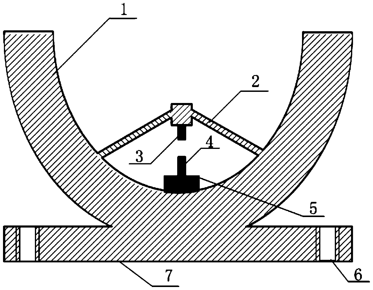
[0033] The present invention provides a preferred embodiment of an underwater plasma sound source directional radiation device such as figure 1 shown. Including rigid hollow parabolic acoustic baffle 1, anode tapered support rod 2, anode discharge electrode 3, cathode discharge electrode 4, cathode insulating medium support platform 5 and flange disc 7; rigid hollow parabolic acoustic baffle 1 bottom and flange The centers of the discs 7 are connected; the flange disc 7 is distributed with threaded through holes 6 for sealing and fixed connection of external plasma sound source equipment; the anode cone support rod 2 is connected with the inner side of the rigid parabolic acoustic baffle 1; the anode cone The center of the shaped support rod 2 is a rectangular platform structure, the tail end of the anode discharge electrode 3 is connected to the center of the rectangular platform structure on the anode conical support rod 2, and the head end of the anode discharge electrode 3...


PUM

PropertyMeasurementUnit
Angleaaaaaaaaaa

Abstract

The invention discloses an sound source radiation device and relates to an underwater plasma sound source directed radiation device, for improving the problems existing in the conventional device thatthe end face of a discharge electrode tip is not ablation resistant, non-uniform in ablation, easy to deform and difficult to replace after damage, the device is poor in own insulating property and water tightness, an energy gathering scheme for improving a peak sound pressure of a plasma sound source is high in operating difficulty and complicated in process, and the like. According to technicalkey points, the underwater plasma sound source directed radiation device disclosed by the invention comprises a rigid parabolic sound barrier, a conical anode supporting rod, an anode discharge electrode, a cathode discharge electrode, a cathode insulating medium supporting table and a flange disc, wherein the bottom of the rigid parabolic sound barrier is connected with the center of the flangedisc; screw holes in sealed fixed connection with an external plasma sound source device are distributed in the flange disc; the conical anode supporting rod is connected with the inner side of the rigid parabolic sound barrier; and corresponding discharge centers at head ends of the anode discharge electrode and the cathode discharge electrode are positioned on the focus of a paraboloid of the rigid parabolic sound barrier.

Description

technical field [0001] The invention relates to a sound source radiation device, in particular to an underwater plasma sound source directional radiation device. Background technique [0002] Underwater plasma sound source, also known as electric spark sound source, its working principle is based on the theory of "hydroelectric effect" proposed by the former Soviet scientist Yutekin, that is, high voltage and high current pulse discharge in liquid medium, resulting in The strong shock wave realizes the radiation of sound energy. The plasma sound source has the characteristics of high power, narrow pulse width, and wide frequency spectrum, and is widely used in the fields of pipeline descaling, sewage treatment, sanitation and disinfection, and marine geological exploration. [0003] The plasma sound source system has a large-capacity energy storage capacitor. During normal operation, it discharges into the underwater electrode channel within microseconds to form a high-temp...

Claims


Application Information

Patent Timeline
IPC IPC(8): G10K15/06G10K11/28
Inventor 曾跃胜陈宏肖开奇樊博宇向龙凤
Owner SOUTHWEST CHINA RES INST OF ELECTRONICS EQUIP
Learn More