Textile needle seat with adjustable spacing

A textile and spacing technology, applied in textiles and papermaking, deburring devices, fiber processing, etc., can solve the problems of large wear, easy to affect the adjustment and use of needle seats, and inconvenient cleaning, etc., to achieve small wear and improve self-cleaning effect Effect

Active Publication Date: 2019-05-14
建德市路达家具有限公司
View PDF8 Cites 3 Cited by
  • Summary
  • Abstract
  • Description
  • Claims
  • Application Information

AI Technical Summary

Problems solved by technology

[0004] The existing wire pay-off device has the following disadvantages: when the position of the slider is adjusted, the spring and the stopper are in direct contact, and the wear is relatively large; On the spring, it affects the expansion and contraction of

Method used


Image

  • Textile needle seat with adjustable spacing
  • Textile needle seat with adjustable spacing
  • Textile needle seat with adjustable spacing

Examples


Embodiment 1

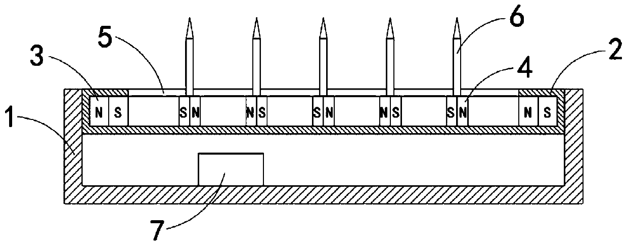
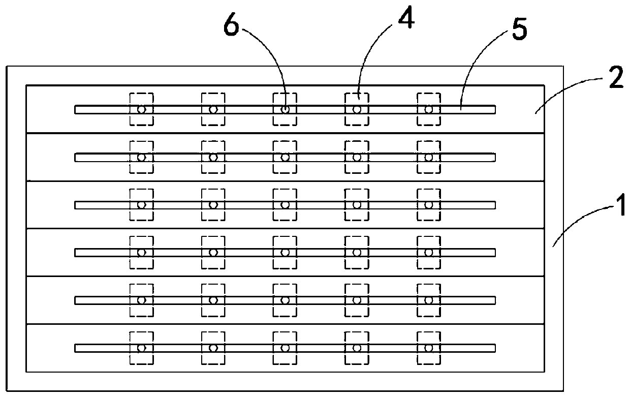
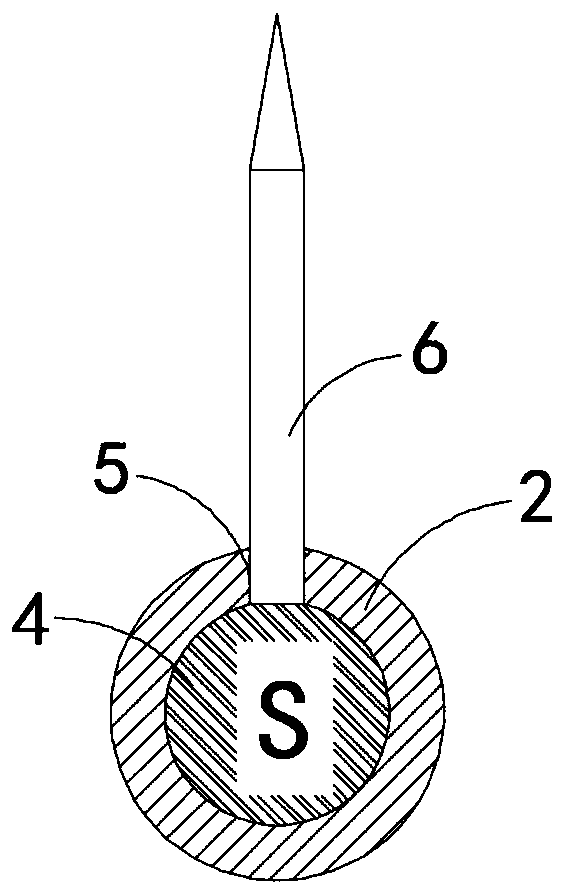
[0026] Such as Figure 1-3 As shown, a textile needle holder with adjustable spacing includes a placement slot 1. In the placement slot 1, a plurality of cylinders 2 arranged side by side and arranged horizontally are fixedly connected. The cylinder 2 is made of a magnetic shielding material to avoid phase differences. There is an influence between the two adjacent cylinders 2. Both ends of the cylinder 2 are fixedly connected with electromagnets 3, and a plurality of permanent magnetic sliders 4 are arranged between the two electromagnets 3. The magnetic induction line of the permanent magnetic slider 4 The direction is parallel to the axial direction of the barrel 2, and the magnetic poles between two adjacent permanent magnetic sliders 4 are opposite. The upper end of the barrel 2 is provided with a strip opening 5, and the upper end of the permanent magnetic slider 4 is fixedly connected with a needle bar 6 , The upper end of the needle bar 6 penetrates through the strip-sha...

Embodiment 2

[0029] Such as Figure 4-6 As shown, the difference between this embodiment and the first embodiment is: a second DC power supply 8 is fixedly installed in the placing slot 1, and the current direction of the second DC power supply 8 is opposite to that of the first DC power supply 7. The power supply 7 and the second DC power supply 8 are coupled with the electromagnet 3 through a pulse switch (such as Image 6 Shown).

[0030] In this embodiment, when the pulse switch is activated, the pulse switch quickly switches back and forth between the first DC power source 7 and the second DC power source 8, so that the magnetic poles of the electromagnet 3 located at both ends of the cylinder 2 are continuously changed, so that The multiple permanent magnetic sliders 4 are continuously separated and gathered together. During the high-frequency switching of the pulse switch, the distance between the adjacent needle bars 6 is continuously changed, causing broken wires or fibers attached be...

Embodiment 3

[0032] Such as Figure 7-8 As shown, the difference between this embodiment and the second embodiment is: an elastic sealing film 9 is fixedly connected between two adjacent permanent magnetic sliders 4, two adjacent permanent magnetic sliders 4, an elastic sealing film 9 and The side walls of the cylinder body 2 jointly form a closed space, the elastic sealing film 9 is provided with a one-way exhaust port 10, and the side wall of the cylinder body 2 is provided with a plurality of one-way air inlets 11, and the side wall of the groove 1 is placed There is a ventilation hole 12 communicating with the outside.

[0033] In this embodiment, when the pulse switch is turned on and the permanent magnet slider 4 moves continuously, the enclosed space becomes larger and smaller, so reciprocating, under the action of the one-way air inlet 11 and the one-way air outlet 10, it can play To the effect of inhalation and blowing, not only can the air below be sucked away, so that the first DC...


PUM


Abstract

The invention belongs to the field of textile, and particularly relates to a textile needle seat with adjustable spacing. The textile needle seat comprises a placing groove, wherein a plurality of cylinders which are arranged side by side and horizontally are fixedly connected into the placing groove; electromagnets are fixedly connected to both ends of the cylinders; a plurality of permanent magnet sliding blocks are arranged between the two electromagnets; the magnetic induction line direction of the permanent magnet sliding blocks is parallel to the axis direction of the cylinders; the magnetic pole directions between the two adjacent permanent magnet sliding blocks are opposite; and strip-shaped openings are formed in the upper ends of the cylinders, the upper ends of the permanent magnet sliding blocks are fixedly connected with needle bars, the upper ends of the needle bars penetrate through the strip-shaped openings and extend to the outside of the cylinders, and a first directcurrent power supply for supplying power to the electromagnets is installed in the placing groove. According to the textile needle seat with the adjustable spacing, the effect of adjusting the needlebar spacing can be achieved by changing the current magnitude of electromagnet energization; and meanwhile, the textile needle seat with the adjustable spacing has a self-cleaning effect, and can automatically clean fibers or broken wires and the like left on the needle seat.

Description

Technical field [0001] The invention belongs to the textile field, and particularly relates to a textile needle holder with adjustable spacing. Background technique [0002] The needle holder is a common equipment used for carding textile materials in the textile field. Depending on the type of textile material, textile needle holders with different pitches are usually used. [0003] After searching, Chinese Patent Authorization No. CN 103952806 B discloses a method for adjusting the pitch of the needle seat of a textile machine, which includes a block-shaped needle seat body and a needle row assembly arranged in the needle seat body. The needle row assembly It includes a long plate, the long plate is provided with slide rails, the two sides of the long plate are provided with stoppers, the slide rails are equidistantly provided with several sliding blocks, and high-pressure springs are arranged between the sliding blocks, The top of the slider is provided with knitting needles. ...

Claims


Application Information

Patent Timeline
IPC IPC(8): D01G15/84
Inventor 何井芳
Owner 建德市路达家具有限公司
Why Eureka
Try Eureka