Injection molding inductor and manufacturing method thereof

An injection molding, inductance technology, used in the manufacture of inductors/transformers/magnets, transformer/inductor shells, signal inductors without magnetic cores, etc. Backing, poor high-frequency characteristics of inductance components, etc., to achieve the effect of simplifying packaging, structure and manufacturing process, and improving production efficiency

Pending Publication Date: 2019-05-14
DONGGUAN SUNLORD ELECTRONICS CO LTD
View PDF19 Cites 1 Cited by
  • Summary
  • Abstract
  • Description
  • Claims
  • Application Information

AI Technical Summary

Problems solved by technology

The inductance component belongs to the traditional large-size power inductor. Since the coil body of the inductance component is provided with an iron core of the first soft magnetic material, it is difficult to reduce its inductance to a small size and low profile.
At the same time, since the iron core adopts the first soft magnetic material, and the injection cladding adopts the second soft magnetic material, although the existence of the first soft magnetic material and the second soft magnetic material restricts the

Method used


Image

  • Injection molding inductor and manufacturing method thereof
  • Injection molding inductor and manufacturing method thereof
  • Injection molding inductor and manufacturing method thereof

Examples


Embodiment 1

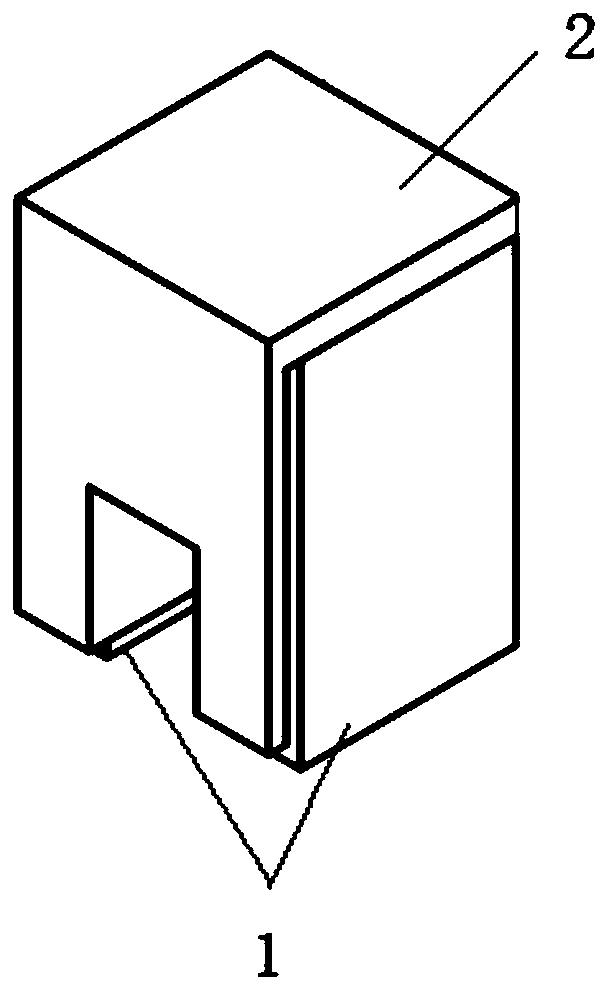
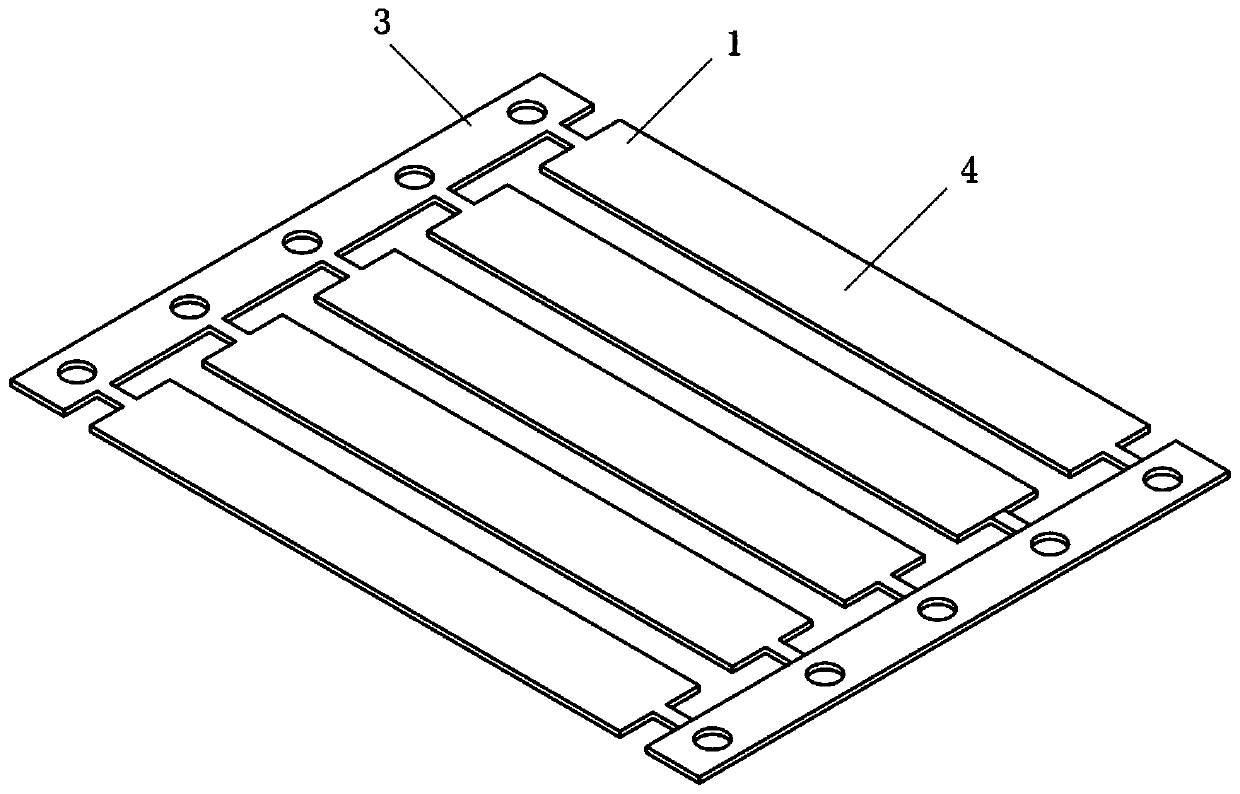
[0061] A small size and low back injection molding inductor suitable for high frequency and high current, reference figure 1 , Figure 3 to Figure 7 . The injection molded inductor includes a copper wire, an electrode, a coil (single turn) and a cladding layer; the copper wire, electrode, and coil are an integral structure before injection molding and are presented in the form of a strip; the copper wire is A flat wire, the two ends of the copper wire are bent to form inductance electrodes; the middle section of the copper wire and the electrodes at both ends form a single-turn coil; the coating layer is made of a polymer insulating material.

[0062] In this specific embodiment, the aforementioned material strip enters the injection molding mold cavity through the assembly line, and the molding coating layer is injected, and then enters the stamping progressive die station through the assembly line to complete the cutting, primary bending, and secondary bending in sequence. Bend...

Embodiment 2

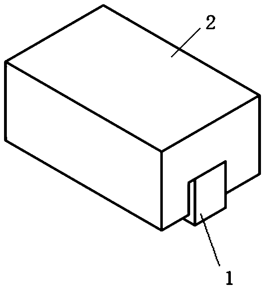
[0064] A small size and low back injection molding inductor suitable for high frequency and high current, reference figure 2 , Figure 8 to Figure 12 . The injection molded inductor includes a copper wire, an electrode, a coil (multi-turn), and a coating layer; the copper wire, electrode, and coil are an integrated structure before injection molding and are presented in the form of a strip; the copper wire is The two ends of the copper wire are bent to form an inductive electrode; the middle section of the copper wire is spot-welded with a flat wire vertical winding multi-turn coil; the coating layer is made of a polymer insulating material.

[0065] In this specific embodiment, the aforementioned material strip enters the injection molding mold cavity through the assembly line, and the molding coating layer is injected, after the magnetic core glue is baked and cured, and then enters the stamping progressive die station through the assembly line to complete the cutting in seque...


PUM


Abstract

The present invention discloses an injection molding inductor and a manufacturing method thereof. The inductor comprises an internal coil, a non-magnetic material covering part formed by covering theinternal coil with a non-magnetic material after injection molding and two external conductors connected to the internal coil and exposed to the non-magnetic material covering part. The invention provides a power inductor which has the advantages of high frequency, large current, small size and easy manufacture.

Description

Technical field [0001] The invention relates to the field of passive magnetic components, in particular to an injection molded inductor and a manufacturing method thereof. Background technique [0002] Common inductors are classified according to their structure: open magnetic circuit inductance, magnetic cover closed magnetic circuit inductance, magnetic glue inductance, metal powder molded integral inductance, assembled flat coil inductance, etc. Different types of inductors have their own advantages and disadvantages, and also limit their applications in specific fields. For example, magnetic glue inductors have less magnetic leakage and low noise interference, but the operating current is generally less than 10A; metal powder molded integrated inductors can achieve larger operating current requirements, but SRF is difficult to meet the GHz requirements. With the development of most electronic devices in the direction of high frequency, large current, and small size, high SRF...

Claims


Application Information

Patent Timeline
IPC IPC(8): H01F17/02H01F27/02H01F27/28H01F27/29H01F41/00
Inventor 洪瑜鹏欧阳过査小月王倩
Owner DONGGUAN SUNLORD ELECTRONICS CO LTD
Why Eureka
Try Eureka