Dual wavelength regression analysis-based optical fiber vibration sensor phase demodulation device and method

A regression analysis and optical fiber vibration technology, applied in the direction of using optical devices to transmit sensing components, measuring devices, instruments, etc., can solve the problems of large phase noise, increase the load of the phase demodulation system, inapplicability, etc., and reduce the sampling rate. requirements, simple structure, and the effect of improving phase accuracy

Active Publication Date: 2019-05-21
WUHAN UNIV OF TECH
View PDF6 Cites 15 Cited by
  • Summary
  • Abstract
  • Description
  • Claims
  • Application Information

AI Technical Summary

Problems solved by technology

At present, most interferometric fiber optic vibration sensors still use single-wavelength interferometric phase demodulation technology. The limitation of this technology is that the optical path difference between two adjacent points cannot change more than half of the wavelength value, so a high sampling rate is required. This has high requirements on the data acquisition system, especially in the long-distance distributed optical fiber vibration sensing system with thousands of fiber grating sensors in series, which greatly increases the load on the phase demodulation system
Subsequently, J.Gass et al. proposed a synthetic wavelength phase demodulation technique (Gass J, Dakoff A, KimM K.Phase imaging without 2πambiguity by multiwavelength digital holography[J]. Optics Letters,2003,28(13):1141-3 .), that is, two sets of interference signals are o

Method used


Image

  • Dual wavelength regression analysis-based optical fiber vibration sensor phase demodulation device and method
  • Dual wavelength regression analysis-based optical fiber vibration sensor phase demodulation device and method
  • Dual wavelength regression analysis-based optical fiber vibration sensor phase demodulation device and method

Examples


Embodiment Construction

[0024] Below in conjunction with specific embodiment the present invention is described in further detail:

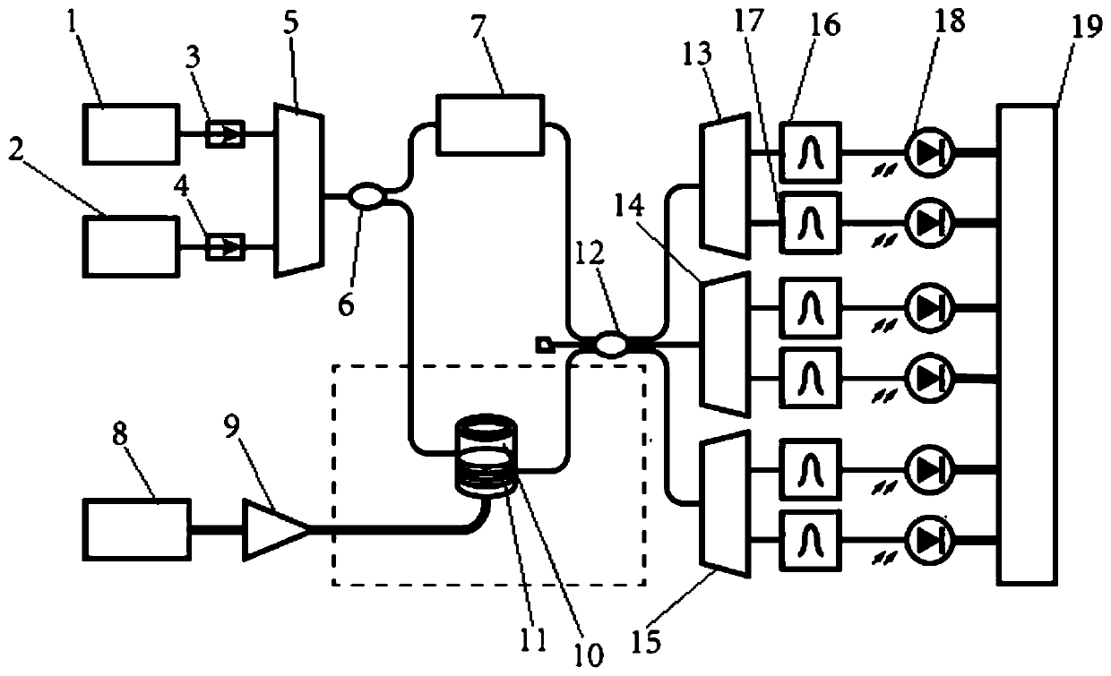
[0025] A kind of optical fiber vibration sensor phase demodulation device based on dual-wavelength regression analysis designed by the present invention, such as figure 1As shown, it includes a first narrow-band laser 1, a second narrow-band laser 2, a tapered wavelength division multiplexer 5, a divide-by-two split coupler 6 (1×2 coupler), and a digitally controlled adjustable optical delay line 7 , ring-shaped piezoelectric ceramic tube 10, three-point three-point coupler 12 (3×3 coupler), the first pull-cone wave demultiplexer 13, the second pull-cone wave demultiplexer 14, the third pull-cone wave demultiplexer A decomposition multiplexer 15 and a multi-channel data acquisition card 19, wherein the outer ring of the ring-shaped piezoelectric ceramic tube 10 is evenly coiled around the vibration sensing optical fiber 11, and the ring-shaped piezoelectric ceramic tube...


PUM


Abstract

The invention relates to a dual wavelength regression analysis-based optical fiber vibration sensor phase demodulation device, which is characterized by comprising a first narrowband laser, a second narrowband laser, a taper wavelength division multiplexer, a coupler, a digitally-controlled dimming delay line, an annular piezoelectric ceramic tube, a three-third coupler, a first taper wavelength division demultiplexer, a second taper wavelength division demultiplexer, a third taper wavelength division demultiplexer and a multi-channel data acquisition card, wherein the outer circle of the annular piezoelectric ceramic tube is uniformly wound with the vibration sensing optical fiber; and the annular piezoelectric ceramic tube can be telescopic periodically under driving of control signals.A dual-wavelength Mach-Zehnder interferometer and a three-third coupler digital phase demodulation technique are used, a dual wavelength regression analysis phase unwrapping principle is adopted, thepi phase limitation principle in the traditional phase unwrapping can be overcome in principle, instantaneous large-scale phase changes caused by actual strong vibration signals are tracked precisely,and a good and single-wavelength interferometry-consistent signal-to-noise ratio level is achieved.

Description

technical field [0001] The invention relates to the technical field of optical fiber sensing, in particular to a phase demodulation device and method for an optical fiber vibration sensor based on dual-wavelength regression analysis. Background technique [0002] Optical fiber has outstanding advantages such as small size, light weight, intrinsic passive safety, etc., and many sensors such as fiber optic accelerometers, fiber optic hydrophones, and fiber optic gyroscopes using this as a medium have developed rapidly. Among them, fiber optic vibration sensors are being studied in depth as an important part of the new generation of vibration sensing systems, and are expected to play an irreplaceable role in geological disaster early warning, hydroacoustic sonar monitoring and other fields. Among various optical fiber vibration sensing forms including intensity, frequency, wavelength, polarization state modulation, etc., the phase modulation type has the highest sensitivity, an...

Claims


Application Information

Patent Timeline
IPC IPC(8): G01H9/00G01D5/353
Inventor 李政颖吴军傅雪蕾桂鑫童宇衡
Owner WUHAN UNIV OF TECH
Why Eureka
Try Eureka