Bipolar battery composite current collector structure and preparation method

A bipolar battery and current collector technology, applied in the field of electrochemical energy storage, to achieve the effect of increasing the payload, expanding the range of the process window, and increasing the cruising range or standby time

Inactive Publication Date: 2019-05-21
CHINA ELECTRONIC TECH GRP CORP NO 18 RES INST
View PDF12 Cites 10 Cited by
  • Summary
  • Abstract
  • Description
  • Claims
  • Application Information

AI Technical Summary

Problems solved by technology

The customer demands in the above aspects pose severe challenges

Method used


Image

  • Bipolar battery composite current collector structure and preparation method
  • Bipolar battery composite current collector structure and preparation method
  • Bipolar battery composite current collector structure and preparation method

Examples


example 1

[0049] Example 1: Preparation and use of carbon-(copper-aluminum)-carbon bipolar current collector

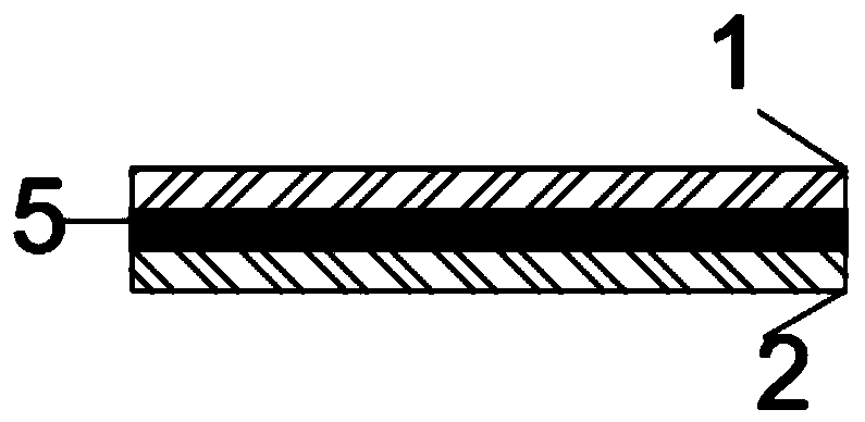
[0050] 1. Determine the surface roughness of the copper and aluminum foil that needs to be processed. Determine the thickness of the protective layer according to the roughness. In this example, a copper-aluminum conductive substrate (5) with a roughness of 400 nm is selected. 2 μm thick carbon protective layers (1) and (2) are respectively deposited on both sides of the copper-aluminum conductive substrate (5).

[0051] 2. Put the selected copper and aluminum foil roll into the winding vacuum chamber.

[0052] 3. Vacuum the sputtering chamber to 10 -6 mbar. Adjust the Ar gas flow rate of the etching target process to a process pressure of 10 -3 mbar, adjust the etching power to 2130kw, and the Ar gas flow at the carbon target position until the process pressure is 10 -3 mbar, sputtering power 1780kw.

[0053] 4. Turn on the heater in the process area to heat the copper ...

example 2

[0061] Example 2: Preparation and use of carbon-aluminum bipolar current collector

[0062] The carbon protective layer deposition process in this example is consistent with the carbon-(copper-aluminum)-carbon bipolar current collector carbon protective layer deposition process.

[0063] 1. Deposit the carbon protective layer (1) on the smooth side of the aluminum conductive substrate (11) using a carbon-(copper-aluminum)-carbon bipolar current collector carbon protective layer deposition process. After deposition, the structure is as Figure 7 shown.

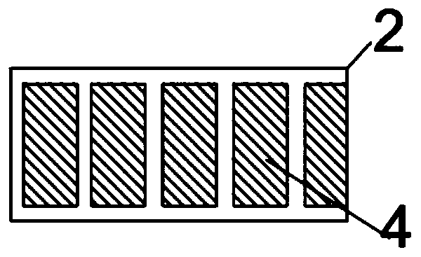
[0064] 2. According to the process requirements, the negative electrode material (3) is coated on the side of the carbon protective layer (1), and the positive electrode material (4) is coated on the side of the aluminum wool surface. Coating shape and structure such as Figure 8 and 9 shown.

[0065] 3. After the coating is completed, follow the Figure 10 The cutout shown is a bipolar electrode sheet, where (12) is the ...


PUM

PropertyMeasurementUnit
Thicknessaaaaaaaaaa
Thicknessaaaaaaaaaa
Roughnessaaaaaaaaaa

Abstract

The invention discloses a bipolar battery composite current collector structure and a preparation method and belongs to the field of electrochemical energy storage technology. The bipolar battery composite current collector structure is characterized in that a protective layer is spread on one side or both sides of a base. The preparation method of the bipolar battery composite current collector structure is characterized in that the protective layer spread on one side or both sides of the base is prepared through physical vapor deposition or chemical vapor deposition or electrochemical deposition or surface fusion or spraying or 3D printing or homogenization. By the adoption of the technical scheme, the bipolar battery composite current collector structure and the preparation method are used for increasing cell energy density and improving cell output characteristics.

Description

technical field [0001] The invention belongs to the technical field of electrochemical energy storage, and in particular relates to a bipolar battery composite current collector structure and a preparation method. Background technique [0002] The development of electrochemical energy is inseparable from people's life and defense industry. Consumer electronics products used in daily life, electric-driven new energy vehicles, and distributed power grids are all inseparable from chemical energy storage. As people's dependence on consumer electronic products increases, the requirements for the standby time of electronic equipment are increasing day by day. On the other hand, the current energy density of mainstream power batteries is about 250-300Wh / Kg, and my country plans to achieve 400Wh / Kg in 2025 for power batteries used in electric vehicles. At the same time, the distributed grid system (especially distributed photovoltaic power generation), which has developed rapidly ...

Claims


Application Information

Patent Timeline
IPC IPC(8): H01M4/66H01M4/04
CPCY02E60/10
Inventor 丁飞赵岳徐睿郝明明张晶王松蕊
Owner CHINA ELECTRONIC TECH GRP CORP NO 18 RES INST
Why Eureka
Try Eureka