a duplexer

A duplexer and resonator technology, which is applied in the field of semiconductors and micro-electromechanical systems, can solve the problems of limiting the overall performance of the filter, the difficulty of guaranteeing the performance of the resonator, and the limited adjustable range, so as to achieve out-of-band suppression and isolation improvement , wide adjustment range, improve the effect of in-band insertion loss

Active Publication Date: 2021-11-30
TIANJIN UNIV +1
View PDF13 Cites 0 Cited by
  • Summary
  • Abstract
  • Description
  • Claims
  • Application Information

AI Technical Summary

Problems solved by technology

However, the frequency of the resonator in the FBAR filter is achieved by adjusting the thickness of the physical layer, the adjustable range is limited, and the performance of the resonator is difficult to guarantee when the adjustment range is too wide
In addition, the piezoelectric coupling coefficient of the resonator basically depends on the thickness and material parameters of the piezoelectric dielectric layer, which is difficult to adjust on the same filter
The limited range of frequency and piezoelectric coupling coefficient limits the improvement of the overall performance of the filter

Method used


Image

  • a duplexer
  • a duplexer
  • a duplexer

Examples


Embodiment 1

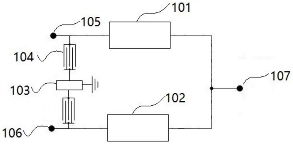
[0057] figure 1 A block diagram of a duplexer according to the first embodiment of the present application is shown. Such as figure 1 As shown, a duplexer includes:

[0058] a transmit filter 101 connected between the transmit terminal 105 and the antenna terminal 107 and comprising series resonators and parallel resonators connected in a trapezoidal form; and

[0059] A receiving filter 102, the receiving filter 102 is connected between the receiving end 106 and the antenna end 107,

[0060] Wherein, the transmitting end 105 and the receiving end 106 respectively lead a branch to the grounding end, and the LWR resonator 104 and the passive device 103 are connected in series in the branch.

[0061] Wherein, each passive device 103 may be a capacitor, an inductor or a resonator. The structure of the passive device 103 may be T-type, pi-type or L-type.

[0062] The above duplexer increases the LWR resonator path between the transmitting end 105 and the receiving end 106, wh...

Embodiment 2

[0091] Figure 7 A block diagram of a duplexer according to the second embodiment of the present application is shown. Such as Figure 7 As shown, a duplexer includes:

[0092] a transmit filter 101 connected between the transmit terminal 105 and the antenna terminal 107 and comprising series resonators and parallel resonators connected in a trapezoidal form; and

[0093] A receiving filter 102, the receiving filter 102 is connected between the receiving end 106 and the antenna end 107,

[0094] Wherein, the transmitting terminal 105 leads a branch to the ground terminal, and the LWR resonator 104 and the passive device 103 are connected in series in the branch.

[0095] Wherein, each passive device 103 may be a capacitor, an inductor or a resonator. The structure of the passive device 103 may be T-type, pi-type or L-type.

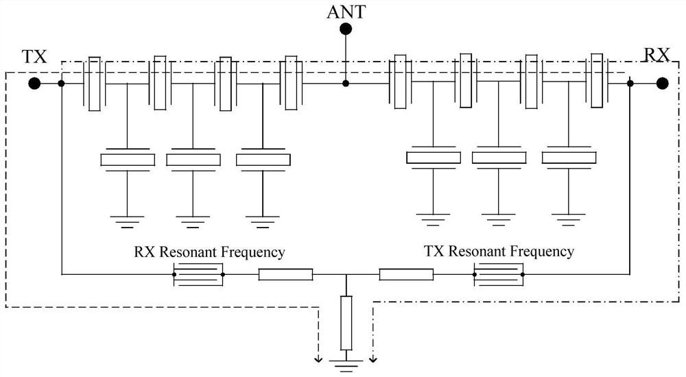
[0096] Figure 8 A circuit structure diagram of a duplexer according to the second embodiment of the present application is shown. Such as Figure...

Embodiment 3

[0105] Figure 11 A block diagram of a duplexer according to the third embodiment of the present application is shown. Such as Figure 11 As shown, a duplexer includes:

[0106] a transmit filter 101 connected between the transmit terminal 105 and the antenna terminal 107 and comprising series resonators and parallel resonators connected in a trapezoidal form; and

[0107] A receiving filter 102, the receiving filter 102 is connected between the receiving end 106 and the antenna end 107,

[0108] Wherein, the receiving terminal 106 leads a branch to the ground terminal, and the LWR resonator 104 and the passive device 103 are connected in series in the branch.

[0109] Wherein, each passive device 103 may be a capacitor, an inductor or a resonator. The structure of the passive device 103 may be T-type, pi-type or L-type.

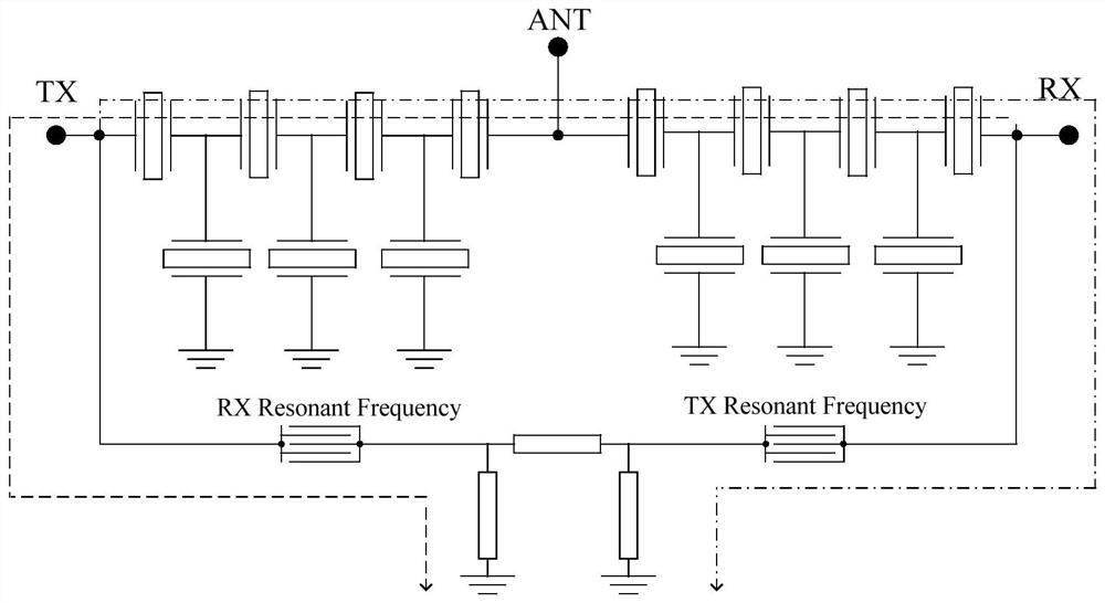
[0110] Figure 12 A circuit structure diagram of a duplexer according to the third embodiment of the present application is shown. Such as Figure 1...


PUM


Abstract

The present invention provides a duplexer, including: a transmitting filter connected between a transmitting end and an antenna end and including series resonators and parallel resonators connected in a trapezoidal form; and a receiving filter, the The receiving filter is connected between the receiving end and the antenna end, wherein, the transmitting end, the receiving end, the antenna end or the transmitting end and the receiving end respectively lead a branch to the ground end, and the LWR resonator and the passive device are connected in series In this branch; the application introduces the LWR resonator in the structural design of the filter and the duplexer to be applied in the structure of the piezoelectric filter and the duplexer to improve the performance of the piezoelectric filter and the duplexer, by Utilizing the impedance characteristics of the LWR resonant frequency point, flexible frequency and the characteristics of piezoelectric coupling coefficient adjustment, different combinations of frequency and piezoelectric coupling coefficient are used to achieve the required impedance transformation at a specific frequency point.

Description

technical field [0001] The invention relates to the field of semiconductors and micro-electromechanical systems, in particular to a duplexer. Background technique [0002] With the rapid development of wireless communication systems, the performance requirements of the RF front-end are becoming more and more stringent. Moreover, the wireless communication system is developing towards the direction of multi-function, multi-band, and multi-protocol, which poses a higher challenge to the RF front-end in wireless communication equipment. As a very important module in the RF front-end, the performance of the filter duplexer plays a decisive role in the performance of the RF front-end. Therefore, there is a very urgent need to continuously improve the performance of the filter duplexer. [0003] In the field of radio frequency communication, Film Bulk Acoustic Wave Resonator (FBAR) has attracted more and more attention due to its small size, high roll-off, and low insertion loss...

Claims


Application Information

Patent Timeline
Patent Type & Authority Patents(China)
IPC IPC(8): H03H7/46H04B1/04
Inventor 庞慰蔡华林
Owner TIANJIN UNIV
Why Eureka
Try Eureka