Oily waste liquid treatment technology in machinery industry

A waste liquid treatment, industry-leading technology, applied in the field of oily waste liquid treatment process in the machinery industry, can solve the problems of reducing the amount of concentrated waste liquid, unstable effluent index, limited water quality range, etc., to optimize the process route and unit equipment, increase heat Transfer efficiency, effect of automatic flushing function design

Inactive Publication Date: 2019-05-28
安洁行方流体管理技术有限公司
View PDF3 Cites 2 Cited by
  • Summary
  • Abstract
  • Description
  • Claims
  • Application Information

AI Technical Summary

Problems solved by technology

At present, strong acid demulsification, coagulation precipitation, photocatalytic oxidation and membrane filtration are generally used for treatment, but the process is complicated and the cost is high, and the treatment effect is not ideal
Among them, the combination of physical and chemical methods requires the addition of chemical agents, resulting in a large amount of scum and sludge, which is likely to cause secondary pollution and increase the difficulty of subsequent treatment; at the same time, the generated slick oil contains impurities and cannot be recycled; and it is not suitable for treatment. Oily waste liquid with high COD; equipment investment cost and operation cost are high; membrane treatment method needs to replace the membrane regularly, and it is easy to cause membrane clogging; in addition, the concentrated waste liquid produced by the membrane treatment method has a high water content, which cannot be minimized The amount of concentrated waste liquid; equipment investment cost and operating cost are high
[0004] The existing treatment process is not only complicated, requires a lot of equipment, large volume, high construction cost, difficult operation and operation technology, unstable effluent indicators, and has relatively large restrictions on oil content of oily waste liquid, the range of water quality that can be adapted is limited , to sum up, it is of great practical significance to seek a new efficient, economical and environmentally friendly treatment method

Method used


Image

  • Oily waste liquid treatment technology in machinery industry

Examples


Embodiment 1

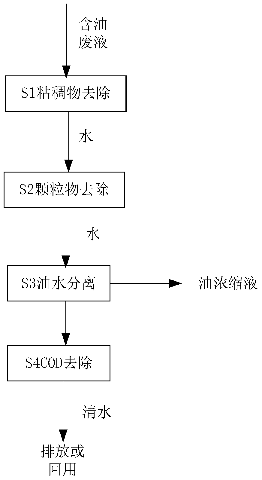
[0035] Waste cleaning liquid from a mechanical processing plant, the waste liquid contains 4% oil, COD value 5000-10000mg / L, suspended solid 1000-3000mg / L, dissolved solid 2000-5000mg / L. The process of the present invention is used to treat the waste cleaning liquid.

[0036] S1: The viscous removal unit is a belt filter, the belt filter adopts a gravity belt filter, the filter cloth is made of ordinary non-woven fabric, the filter cloth precision is 10μm, and viscous and cuttings such as slick oil and paraffin can be removed effective retention. After the oily waste liquid enters the belt filter, it passes through the filter cloth under the action of gravity, the viscous matter is isolated and attached to the filter cloth, and the filtrate enters the liquid tank, and the removal efficiency of the viscous matter is >95%. The belt filter is equipped with a dirt collection box to collect the replaced filter cloth and the sticky matter attached. The belt filter monitors the fil...

Embodiment 2

[0041] Waste cutting fluid from an auto parts processing factory, the waste fluid contains 5% oil, COD value 20000-35000mg / L, suspended solid 3000-6000mg / L, dissolved solid 5000-10000mg / L. The waste cutting fluid is treated by the system of the present invention.

[0042] S1: The viscous removal unit is a belt filter, the belt filter adopts a gravity belt filter, the filter cloth is made of ordinary non-woven fabric, the filter cloth precision is 10μm, and viscous and cuttings such as slick oil and paraffin can be removed effective retention. After the oily waste liquid enters the belt filter, it passes through the filter cloth under the action of gravity, the viscous matter is isolated and attached to the filter cloth, and the filtrate enters the liquid tank, and the removal efficiency of the viscous matter is >95%. The belt filter is equipped with a dirt collection box to collect the replaced filter cloth and the sticky matter attached. The belt filter monitors the filter ...


PUM

PropertyMeasurementUnit
iodine adsorption valueaaaaaaaaaa
specific surface areaaaaaaaaaaa
chemical oxygen demand (mass)aaaaaaaaaa

Abstract

The invention relates to the fields of environmental governance, energy conservation and emission reduction, in particular to an oily waste liquid treatment technology in machinery industry. A methodcomprises the following steps: removing of a sticky matter, removing of particulate matters, oil-water separation and removing of COD (Chemical Oxygen Demand), and a cascade technological route for sequentially removing the sticky matter, the particulate matters, oil and the COD in oily waste liquid is formed. Design optimization is carried out according to the difficulty of impurity removing andthe influence to downstream equipment and treatment efficiency, a filter core type filter is enabled not to be blocked due to removing of the sticky matter in advance, scaling in an evaporator can bereduced through the removing of the particulate matters, and the treatment efficiency of equipment is increased while the equipment is protected; a pure physical method is adopted, no chemical agent is added, generation of oily sludge is avoided, and secondary pollution and input of aftertreatment are reduced; the operating efficiency and the energy utilization rate are high, the applicable waterquality range is wide, and effluent indexes are stable; the investment is saved, and meanwhile, the operating cost is low; an oil concentrated solution can be further subjected to resource utilization, and dual benefits of environment protection and resource saving are realized.

Description

technical field [0001] The invention relates to the field of environmental governance, energy saving and emission reduction, in particular to a process for treating oily waste liquid in the machinery industry. Background technique [0002] The oily waste liquid in the machinery industry mainly refers to the waste emulsion, waste cutting fluid, and oily waste liquid produced in the process of mechanical processing, as well as the oily waste liquid produced in lubrication, cooling, and transmission systems; the oily waste liquid produced in the cleaning process before and after machining of mechanical parts; the mechanical processing workshop Oily waste liquid discharged from washing the ground, equipment, etc.; waste liquid generated during the maintenance and cleaning of equipment in the mechanical repair workshop, etc. These oily waste liquids contain emulsifiers, which belong to the oil-in-water emulsification system, and their main components are machine oil or mineral oi...

Claims


Application Information

Patent Timeline
Patent Type & Authority Applications(China)
IPC IPC(8): C02F9/10
Inventor 张虎刘小明
Owner 安洁行方流体管理技术有限公司
Why Eureka
Try Eureka