Laser cleaning process monitoring method based on acoustic emission technology

An acoustic emission technology and laser cleaning technology, which are used in material analysis, cleaning methods and utensils, chemical instruments and methods using acoustic emission technology, etc., can solve the problems of expensive equipment, poor anti-interference ability, and cumbersome signal processing. The effect of cheap equipment, improved reliability, and simple signal processing

Active Publication Date: 2019-05-28
GUANGDONG UNIV OF TECH
View PDF2 Cites 10 Cited by
  • Summary
  • Abstract
  • Description
  • Claims
  • Application Information

AI Technical Summary

Problems solved by technology

Related to the practical application of laser cleaning technology, such as traditional spectral analysis technology and CCD optical imaging technology and other monitoring technologies, the equipment is expensive, the anti-interference ability is poor, and the signal processing is cumbersome.

Method used


Image

  • Laser cleaning process monitoring method based on acoustic emission technology
  • Laser cleaning process monitoring method based on acoustic emission technology
  • Laser cleaning process monitoring method based on acoustic emission technology

Examples


Embodiment 1

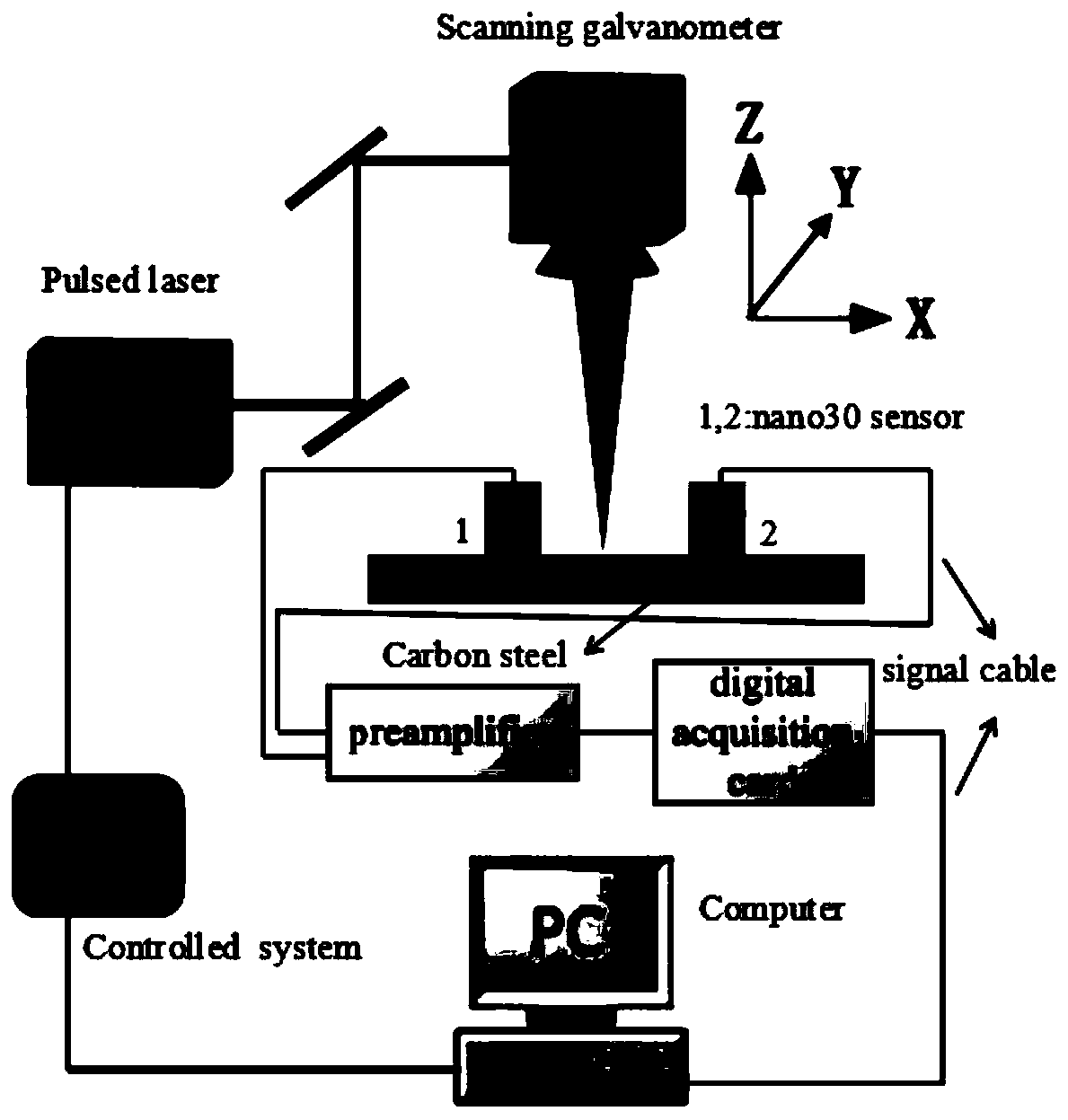
[0040] Such as Figure 1 to Figure 5 As shown, this embodiment discloses a laser cleaning process monitoring method based on acoustic emission technology, the monitoring method mainly includes the following specific steps:

[0041] Step S1: Place and position the carbon steel sample on the nanosecond near-infrared fiber laser X / Y / Z workbench, and focus the laser so that the spot focus is on the surface of the carbon steel rust layer.

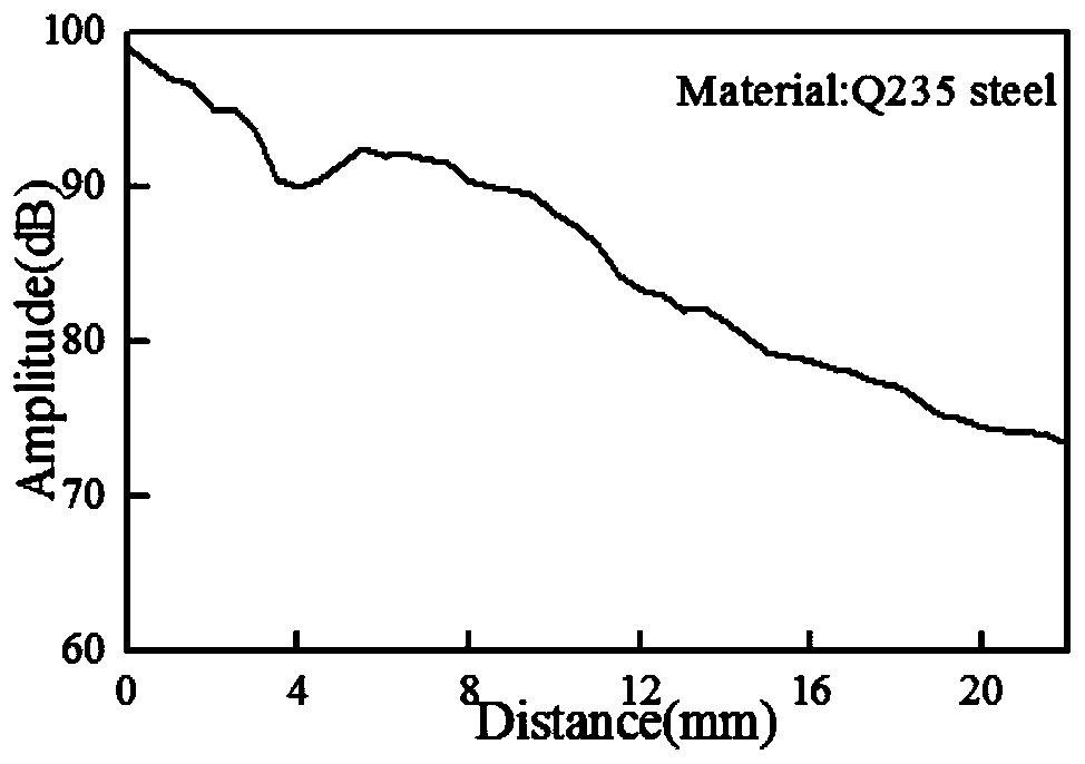
[0042] Step S2: then place the sensor, perform an amplitude curve measurement test according to the attenuation characteristics of the acoustic emission signal of the rusted layer of the workpiece, and determine that the sensor is coated with vaseline and placed at a distance of 8mm from the acoustic emission source (rust removal area).

[0043] Step S3: Build the acoustic emission detection device, use the signal cable to connect the sensor to the preamplifier, connect the output end of the preamplifier to the PCI-2 data acquisition card, and s...

Embodiment 2

[0059] Such as Figures 1 to 5 As shown, this embodiment discloses an acoustic emission monitoring method in a pulsed laser cleaning process with simple structure and use, high precision and stable performance, so as to solve the problem that the existing laser cleaning technology does not have real-time detection and improve the cleaning efficiency. The conundrum of quality and efficiency.

[0060] To achieve the above object, the present invention takes the following technical solutions:

[0061] (1) Real-time monitoring system for pulsed laser cleaning process based on acoustic emission technology, see figure 1 , characterized in that it includes a near-infrared nanosecond fiber laser processing system, a PCI-2 data acquisition card, two preamplifiers, and two acoustic emission nano-30 resonant sensors; the acoustic emission sensor is installed on the rust of the workpiece, The output channel of the sensor is connected to the input channel of the preamplifier, and the ou...


PUM


Abstract

The invention discloses a laser cleaning process monitoring method based on an acoustic emission technology. A monitoring system is composed of a near-infrared nanosecond optical fiber laser processing system, a data acquisition card, preamplifiers, a signal cable and acoustic emission sensors. According to the principle of the laser cleaning process monitoring method, the cleaning effect is subjected to real-time and non-destructive monitoring based on the laser cleaning process of the acoustic emission technology; a mutual mathematical relation between the cleaning effect (the quantity of residual rust materials on the surfaces of workpieces) and the amplitude of acoustic emission signals is obtained, setting of laser processing parameters is controlled in real time, and thus laser cleaning is subjected to online and non-destructive monitoring; besides, the acoustic emission sensors are directly arranged on the surfaces of rust layers of the workpieces, the interference of other signals is reduced, and the reliability of the collected acoustic emission signals is improved. According to the monitoring system and method, the structure and use are very simple and reasonable, the precision is high, the performance is stable, the problem that an existing laser cleaning technology does not have a real-time detection function is solved, and the cleaning quality and efficiency are improved.

Description

technical field [0001] The invention relates to the technical field of monitoring the laser cleaning process, in particular to the monitoring technology of the laser cleaning process. Background technique [0002] Laser cleaning technology uses pulsed laser with high peak power to irradiate the surface of the workpiece, so that the pollutants, rust or paint layer on the surface absorb laser energy and then peel off or evaporate instantly after a series of changes, and finally be effectively removed from the substrate. Compared with the traditional cleaning process, laser cleaning has obvious advantages. The main performance is that the non-mechanical contact process will not cause mechanical damage to the workpiece. The laser directionality is good, which can achieve precise positioning of the cleaning area and can adapt to complex curved surfaces. It has no flying dust. pollution, energy saving and environmental protection. [0003] However, the mechanism of laser cleaning...

Claims


Application Information

Patent Timeline
Patent Type & Authority Applications(China)
IPC IPC(8): G01N29/14G01N29/11B08B7/00
Inventor 谢小柱黄庆澎
Owner GUANGDONG UNIV OF TECH
Why Eureka
Try Eureka