A voltage injection type sic MOSFET active drive circuit

A voltage injection, source-driven technology, applied in the field of power electronics, can solve problems such as increased switching loss, increased driving resistance, increased switching loss, etc., to solve voltage spikes and oscillations, suppress voltage spikes and oscillations, and solve the effect of electromagnetic interference

Active Publication Date: 2020-06-16
BEIJING JIAOTONG UNIV
View PDF7 Cites 0 Cited by
  • Summary
  • Abstract
  • Description
  • Claims
  • Application Information

AI Technical Summary

Problems solved by technology

On the one hand, it can be suppressed by optimizing the PCB layout and reducing the stray inductance of the line. This method requires high hardware design knowledge of electronic circuits; on the other hand, increasing the gate resistance can reduce or even eliminate this situation , but the increase of the driving resistance slows down the switching speed and increases the switching loss, which is not suitable for use in high-frequency converters; in addition, snubber circuits and active clamps can also effectively suppress voltage spikes and oscillations, but additional power circuits Components such as capacitors or inductors will increase the loss of the power circuit side, which will increase the loss of the power converter
In summary, although the above methods can suppress voltage spike oscillations to a certain extent, the increase in switching loss is huge and cannot fully demonstrate the advantages of SiC MOSFET devices.

Method used


Image

  • A voltage injection type sic MOSFET active drive circuit
  • A voltage injection type sic MOSFET active drive circuit
  • A voltage injection type sic MOSFET active drive circuit

Examples


Embodiment Construction

[0020] The embodiments of the present invention are described in detail below. Examples of the embodiments are shown in the accompanying drawings, in which the same or similar reference numerals indicate the same or similar elements or elements with the same or similar functions. The embodiments described below with reference to the accompanying drawings are exemplary, and are intended to explain the present invention, but should not be construed as limiting the present invention.

[0021] The voltage injection type SiC MOSFET active driving circuit proposed according to the embodiments of the present invention will be described below with reference to the accompanying drawings.

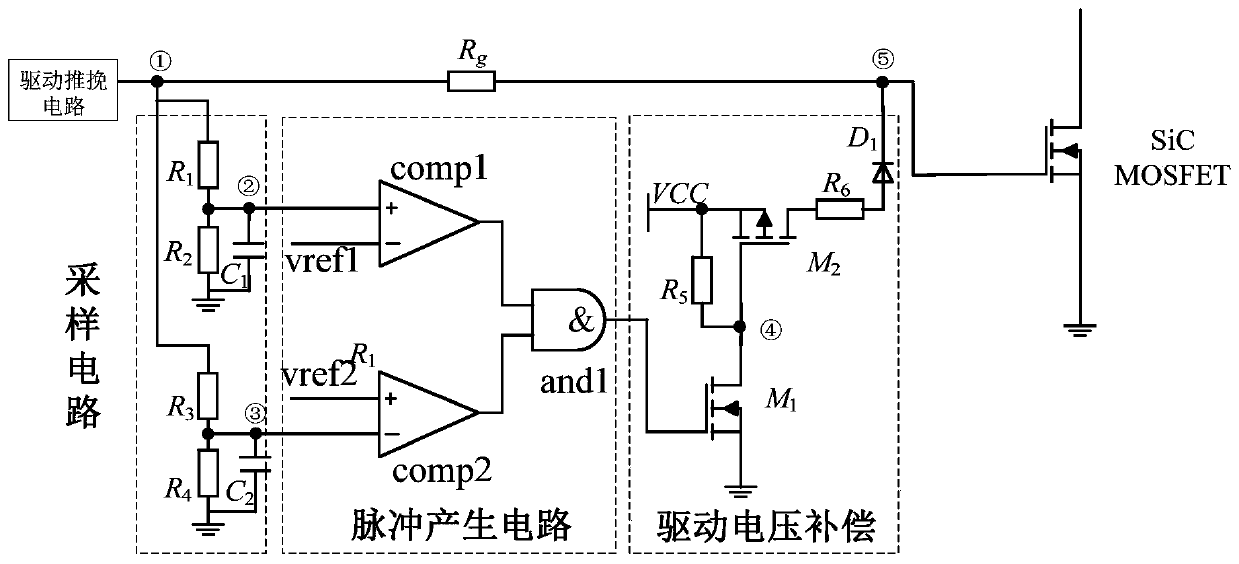
[0022] figure 1 It is a schematic structural diagram of a voltage injection type SiC MOSFET active driving circuit according to an embodiment of the present invention.

[0023] Such as figure 1 As shown, the voltage injection type SiC MOSFET active driving circuit includes: a driving push-pull circuit, a dr...


PUM


Abstract

The invention discloses a voltage injection type SiC MOSFET active driving circuit. The voltage injection type SiC MOSFET active driving circuit includes a driving push-pull circuit, a driving resistor, a sampling circuit, a pulse generation circuit and a driving voltage compensation circuit, wherein the sampling circuit comprises a first resistor, a second resistor, a third resistor, a fourth resistor, a first capacitor and a second capacitor, the pulse generation circuit comprises a first comparator, a second comparator and a first logic AND gate, and the driving voltage compensation circuitcomprises a fifth resistor, a sixth resistor, a first switch tube, a second switch tube and a first diode. According to the active driving circuit provided by the embodiment of the invention, the sampling circuit detects the driving pulse, so that the pulse generation circuit generates a compensation signal in the drain current drop stage in the SiC MOSFET turn-off process; Through the driving voltage compensation circuit, the gate voltage is compensated to raise the gate voltage and inhibit the change rate of the current so as to inhibit the voltage peak and oscillation at the two ends of the SiC MOSFET.

Description

Technical field [0001] The present invention relates to the technical field of power electronics, in particular to a voltage injection type SiC MOSFET active driving circuit. Background technique [0002] The application of traditional silicon devices in converters has reached the limit of silicon materials, which has become a bottleneck for the development of switching converters in pursuit of high stability, high efficiency, high frequency and high power density. In the past ten years, silicon carbide devices have developed rapidly. Compared with silicon devices, silicon carbide devices have higher voltage blocking capabilities, better heat resistance, lower on-resistance and faster switching performance. So it is widely used in switching converters. Due to the inherent lead inductance in the circuit, the faster switching speed of the silicon carbide device will cause higher voltage spikes and oscillations across the power device. The voltage spikes and oscillations at both e...

Claims


Application Information

Patent Timeline
Patent Type & Authority Patents(China)
IPC IPC(8): H03K17/081
Inventor 李虹蒋艳锋冯超杨志昌赵星冉
Owner BEIJING JIAOTONG UNIV
Why Eureka
Try Eureka