MIMO radar detection method and device based on double optical frequency combs and difference frequency multiplexing

A detection method and technology of optical frequency comb, applied in the field of microwave photonic radar detection, can solve problems such as inability to guarantee system coherence, limited subsequent signal processing, complex structure, etc., to improve frequency band utilization and azimuth resolution, The effect of reducing the requirement of the sampling rate and increasing the azimuth resolution

Active Publication Date: 2019-05-28
NANJING UNIV OF AERONAUTICS & ASTRONAUTICS
View PDF5 Cites 18 Cited by
  • Summary
  • Abstract
  • Description
  • Claims
  • Application Information

AI Technical Summary

Problems solved by technology

However, this method needs to generate M local oscillator signals of different frequencies, and needs to use M modulators. The structure is complex and the cost is high. At the same time, the coherence of the system cannot be guaranteed, which limits the subsequent signal processing.

Method used


Image

  • MIMO radar detection method and device based on double optical frequency combs and difference frequency multiplexing
  • MIMO radar detection method and device based on double optical frequency combs and difference frequency multiplexing
  • MIMO radar detection method and device based on double optical frequency combs and difference frequency multiplexing

Examples


Embodiment Construction

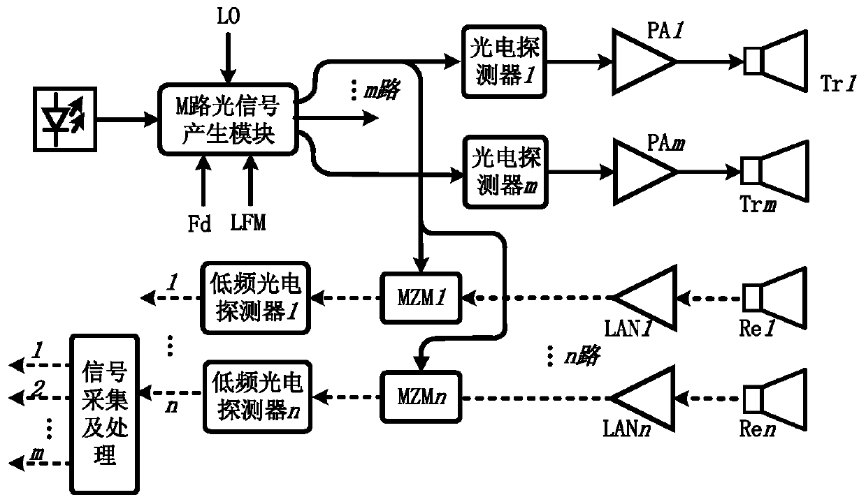
[0042] Aiming at the deficiencies of the existing MIMO radar detection technology based on microwave photon orthogonal difference frequency multiplexing, the solution of the present invention is to improve the transmitting end and use the dual optical frequency comb scheme to generate difference frequency signals, so as to improve the utilization rate of the frequency band , improve the azimuth resolution of the radar, reduce the requirement on the sampling rate, and at the same time greatly simplify the structure of the transmitter, reduce the cost of system implementation, and effectively ensure the coherence between the various signals.

[0043] The MIMO radar detection method based on dual optical frequency combs and difference frequency multiplexing proposed by the present invention is as follows:

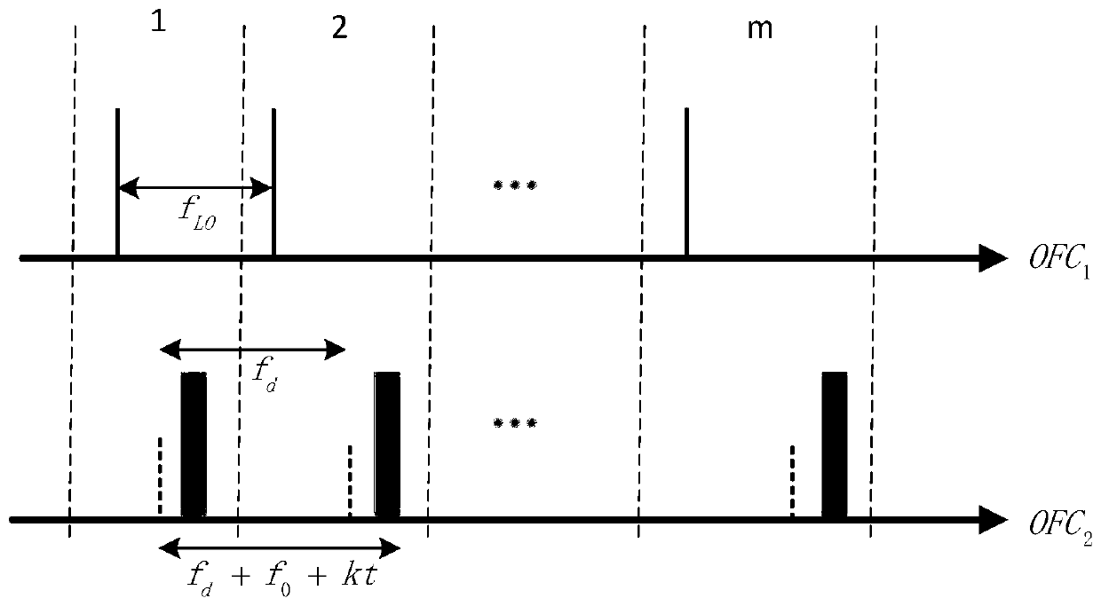
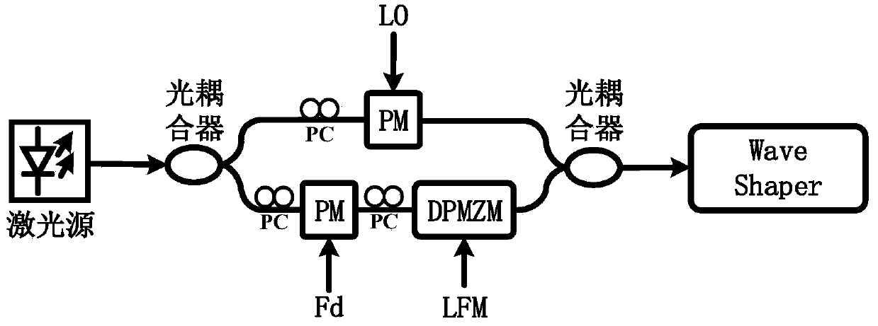
[0044] At the transmitting end, M channels of modulated optical signals are first generated, and the beam-split modulated optical signals of one channel of modulated optical si...


PUM


Abstract

The invention discloses an MIMO radar detection method based on double optical frequency combs and difference frequency multiplexing. According to the method, an existing MIMO radar detection technology based on microwave photon orthogonal difference frequency multiplexing is improved, and M paths of modulated optical signals of a transmitting end are generated through the following method: firstly, an optical carrier is divided into an upper path and a lower path; The local oscillator signal is used for carrying out modulation processing on the uplink optical carrier wave to generate a firstoptical frequency comb signal, and the intermediate frequency signal and the intermediate frequency linear frequency modulation signal are used for carrying out modulation processing on the next optical carrier wave to generate a second optical frequency comb signal; After the first optical frequency comb signal and the second optical frequency comb signal are coupled into one path, the first optical frequency comb signal and the second optical frequency comb signal are divided into M paths of modulated optical signals respectively consisting of a single intermediate frequency linear frequencymodulation spectrum line and a single local oscillator signal spectrum line through beam shaping filtering. The invention also discloses an MIMO radar detection device based on the double optical frequency combs and the difference frequency multiplexing. According to the invention, the structure of the transmitter can be greatly simplified, the implementation cost of the system is reduced, and the coherence between signals can be effectively ensured.

Description

technical field [0001] The invention relates to a microwave photon radar detection method, in particular to a microwave photon MIMO (Multiple-Input Multiple-Output, multiple-input multiple-output) radar detection method with difference frequency multiplexing and a microwave photon MIMO radar device. Background technique [0002] The use of modern radar is highly diversified, including air traffic control, vehicle collision avoidance and meteorological precipitation detection, etc. High precision, high resolution and real-time multi-target detection have always been the development direction of radar. High-resolution imaging requires the support of large-bandwidth transmission signals, MIMO technology and high-speed sampling systems (see [Pan Shilong, Zhu Dan, Zhang Fangzheng. Microwave Photonics for Modern Radar Systems[J]. Transactions of Nanjing University of Aeronautics and Astronautics, 2014, 31 (03):219-240.]). [0003] Multiple input multiple output (MIMO) radar is a ...

Claims


Application Information

Patent Timeline
Patent Type & Authority Applications(China)
IPC IPC(8): H04B10/516H04B10/61H04B10/80H04B10/40
Inventor 丁杰文周悦雯潘时龙张浩
Owner NANJING UNIV OF AERONAUTICS & ASTRONAUTICS
Why Eureka
Try Eureka