
Double-head and double-sided friction stir welding equipment with high efficiency, and welding method thereof
A friction stir welding, high-efficiency technology, applied in the direction of welding equipment, welding equipment, non-electric welding equipment, etc., can solve the problems of not being large-scale, and the overall welding process is not effective, so as to reduce the contact area, save grinding and turning The time and the effect of improving welding efficiency
- Summary
- Abstract
- Description
- Claims
- Application Information
AI Technical Summary
Problems solved by technology
Method used
Image

Examples
Embodiment 1
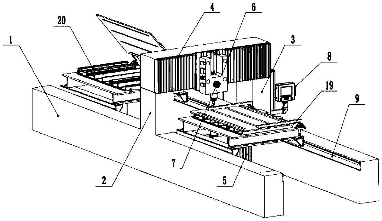
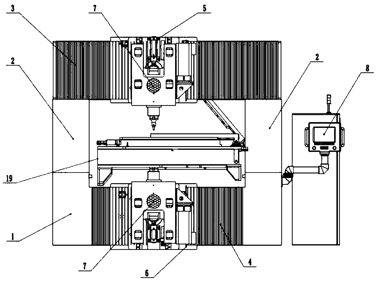
[0040] Embodiment 1: as figure 1 , 3 , 4, the friction stir welding equipment of this embodiment comprises: a base 1, a pair of columns 2 arranged on the base 1, an upper beam 3 connected to the top of the column 2, an upper head 5 is arranged on the upper beam 3, The lower crossbeam 4 connected between the lower ends of the columns 2 is provided with a lower head 6 corresponding up and down with the upper head 5 on the lower crossbeam 4 .
[0041] Among them, the column 2, the upper beam 3 and the lower beam 4 form a gantry frame with an integral structure, and the upper machine head 5 and the lower machine head 6 can move along the X axis, Y axis and Z axis through the driving device and the transmission mechanism, and move along the Z axis. Rotation, the movement of the upper head 5 and the lower head 6 on the X-axis and Y-axis is driven by a linear motor, and the screw guide rail or rack-and-pinion guide rail is driven. The upper head 5 and the lower head 6 can move on th...
Embodiment 2
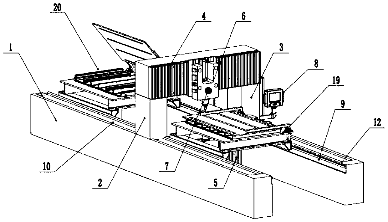
[0049] Embodiment 2: as figure 2 , 3 As shown in . The lower crossbeam 4 connected between the lower ends of the columns 2 is provided with a lower head 6 corresponding up and down with the upper head 5 on the lower crossbeam 4 .
[0050] Among them, the column 2, the upper beam 3 and the lower beam 4 form a gantry frame with an integral structure, and the upper machine head 5 and the lower machine head 6 can move along the X axis, Y axis and Z axis through the driving device and the transmission mechanism, and move along the Z axis. Rotation, the movement of the upper head 5 and the lower head 6 on the X-axis and Y-axis is driven by a linear motor, and the screw guide rail or rack-and-pinion guide rail is driven. The upper head 5 and the lower head 6 can move on the Z-axis. Servo electric cylinder, hydraulic pressure, lead screw, size rack and other transmission methods are adopted. The upper head 5 and the lower head 6 can be rotated on the Z axis by electric spindle or m...
Embodiment 3
[0058] Embodiment 3: This embodiment is basically the same as Embodiment 1, the difference is:
[0059] (1) The end of the friction stirring head 16 of the present embodiment is provided with an anti-wear gasket 17, and the preparation method of the anti-wear gasket 17 is: 80% tungsten carbide powder, 6% alumina fiber, 7% titanium dioxide powder, 3% Vanadium oxide powder and 4% graphite powder are mixed and smelted into a liquid alloy at 3000°C. The femtosecond laser is used to irradiate disorderly. The repetition frequency of the femtosecond laser is 95MHz, and the frequency of the chopper is adjusted to 4000Hz. The number of femtosecond pulses in the cycle is about 18776, and the irradiation time is 6 minutes. Then the liquid alloy is gradually cooled to a solid state, and then remelted. The above operation is repeated for a total of 6 times, followed by casting and forging to obtain an anti-wear bar after internal remodeling. ; Weld the anti-wear bar and the end of the fric...
PUM
| Property | Measurement | Unit |
|---|---|---|
| thickness | aaaaa | aaaaa |
Abstract
Description
Claims
Application Information