Bolt shearing force connecting piece with weakened section

A technology of connectors and bolts, which is applied in the field of construction engineering, can solve problems such as poor deformation capacity, small deformation capacity of bolts, and failure to solve the damage position, so as to improve ductility and deformation capacity, good connection and shear resistance, and save manpower and material resources Effect

Pending Publication Date: 2019-05-31
TIANJIN UNIV
View PDF13 Cites 3 Cited by
  • Summary
  • Abstract
  • Description
  • Claims
  • Application Information

AI Technical Summary

Problems solved by technology

[0004] Chinese patent CN203755452U discloses "a bolt shear connection", which is based on a traditional bolt shear connection, a spring is arranged around the screw, and the bottom of the nut at the top of the screw and the top of the upper flange of the steel beam and the end of the spring are welded. In addition The method of connecting springs enhances the stiffness and shear strength of the shear connectors, but lacks deformation capacity. The screw is prone to brittle fracture at the contact surface between the concrete slab and the steel beam flange, which cannot solve the problem of the failure position, and the components must be welded and purchased. Spring, increasing cost
[0005] Chinese patent CN202227584U announced the "non-welded high-strength bolt shear key structure". Failure to effectively address the failure location and poor deformability
[0006] Chinese patent CN205329851U announced "a new type of bolt sleeve shear connector". Its construction principle is to set a straight thread sleeve on the threaded part on the upper side of the upper flange of the steel beam, and weld it with the flange of the steel beam. This technology requires the purchase of steel sleeves The cylinder still needs to be welded, the cost is high, and the rigidity is too large, resulting in poor deformation ability
[0007] To sum up, when bolted shear connectors are used as shear connectors of detachable assembled composite beams, there are the following problems: (1) Screws are usually made of high-strength steel, which is much stronger than traditional welded studs. Ordinary steel has high strength, but its material is brittle, with low ductility and small elongation, which leads to small deformation capacity of bolts as shear connectors, which affects the redistribution of internal forces between steel beams and concrete slabs in composite beams and the overall integrity of composite beams. Deformation capacity; (2) When the failure mode of screw shear occurs in the bolted shear connection, the shear section of the screw is usually located at the interface between the bottom surface of the concrete slab and the top surface of the flange of the steel beam, where there are threads on the ring surface of the screw
(3) Shear failure occurs in the thread section of the bolt. The deformation of the screw in this section is too large or the local pressure damage to the screw hole of the flange of the steel beam causes excessive deformation, which will increase the construction difficulty of the later disassembly work and is not conducive to the circulation of the component use
(4) Externally connecting parts that can increase the cross-sectional area of ​​the traditional high-strength bolt shear connection can increase its stiffness and strength, but it also reduces its deformation capacity and is prone to brittle fracture, and some external parts still need to be welded. Both greatly increase the cost

Method used


Image

  • Bolt shearing force connecting piece with weakened section
  • Bolt shearing force connecting piece with weakened section
  • Bolt shearing force connecting piece with weakened section

Examples


Embodiment Construction

[0019] The present invention will be described in detail below in conjunction with the accompanying drawings and specific embodiments.

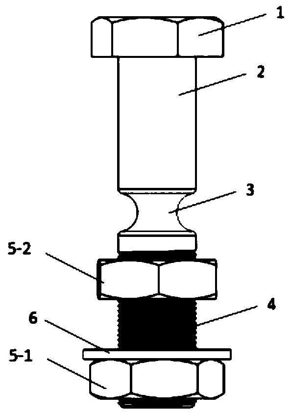
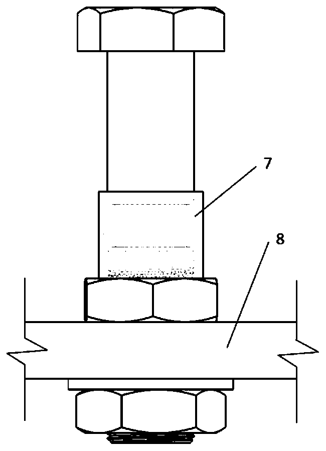
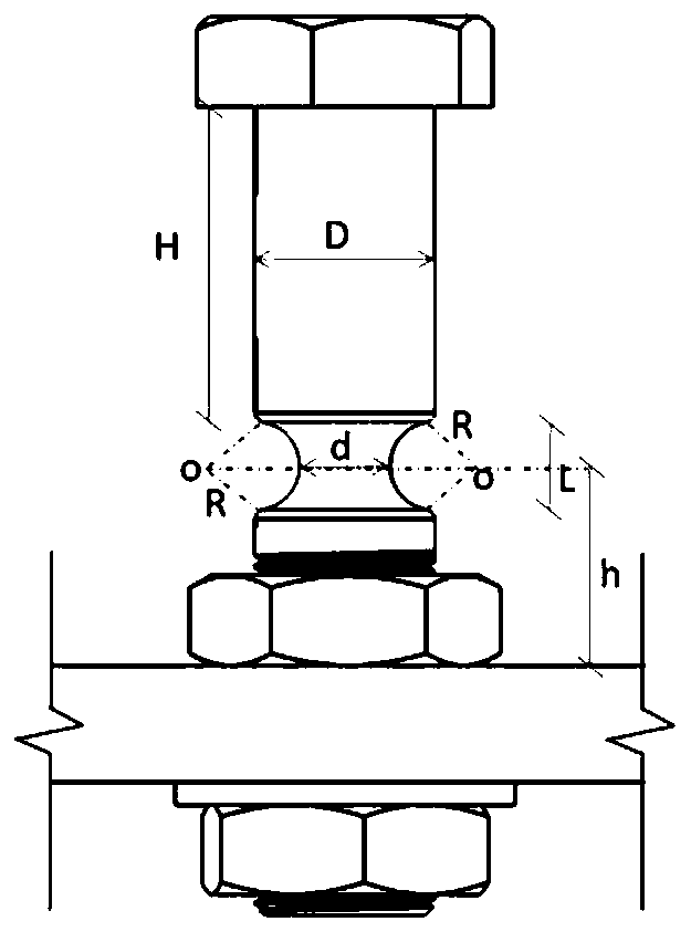
[0020] Such as figure 1 , 2 As shown, a bolt-weakened bolt shear connector includes a bolt with a nut 1 on the top, and the bolt includes an upper smooth rod section 2, a necked rod section 3, The diameter of the lower smooth rod section and the threaded rod section 4, the diameter of the upper smooth rod section 2, the diameter of the lower smooth rod section and the outer diameter of the threaded rod section 4 are consistent. The minimum cross-sectional diameter of the necking rod section 3 is smaller than the inner diameter of the threaded rod section 4, and a lower nut 5-1 and a washer 6 are threadedly connected to the lower part of the threaded rod section. An upper nut 5-2 is threadedly connected to the upper part, and a plastic screw sleeve 7 is set on the necking rod section 3 . The plastic screw sleeve 7 should have a wall thickne...


PUM


Abstract

The invention discloses a bolt shearing force connecting piece with a weakened section. A screw cap, a threaded rod, a thread, a nut, a gasket and a plastic threaded rod sleeve are included. The threaded rod is provided with the screw cap. A symmetric necking-down rod section with the cross section area gradually reduced and then gradually increased needs to be machined in a threaded rod smooth rod section between the thread top on the upper side of a steel beam flange and the screw cap. When the bolt shearing force connecting piece serves as a shearing force connecting piece to be applied toa combined beam, the necking-down rod section needs to approach the position of an upper nut body of an upper flange of a steel beam, the threaded rod penetrates through a hole formed in the steel beam flange in advance and is fastened to the steel beam flange through the upper nut body and a lower nut body, and the gasket is arranged between the lower face of the steel beam flange and the lower nut body. According to the bolt shearing force connecting piece, the reliable anti-shearing strength of the bonding surface of the steel beam and a concrete panel is guaranteed, meanwhile, rigidity ofthe necking-down rod section is reduced, the deformation capability of the bolt shearing force connecting piece is increased, and brittle fracture of the bolt shearing force connecting piece is avoided; and a damaged position is induced to the transferred to the necking-down rod section, and deformation not facilitating later detachment is prevented from being generated to the steel beam and a bolt of the threaded rod section.

Description

technical field [0001] The invention relates to a steel-concrete composite beam, in particular to a shear connector for a joint surface of steel and concrete in a composite beam, and belongs to the field of construction engineering. Background technique [0002] Steel-concrete composite beams can give full play to the advantages of good tensile properties of steel and high compressive strength of concrete, so they have excellent mechanical properties and high economic efficiency. In the steel-concrete composite beam, the steel beam and the concrete slab are combined to bear the force together through the shear connector, and the shear connector is the key component in the composite beam. At present, welded studs are usually used as shear connectors in composite beams in engineering circles. Welded stud shear keys have the advantages of simple structure and the same shear resistance in all directions, but at the same time, there are problems such as troublesome construction,...

Claims


Application Information

Patent Timeline
Patent Type & Authority Applications(China)
IPC IPC(8): F16B37/02F16B35/00F16B31/06F16B5/02E04C3/294
Inventor 罗云标齐连训孙硕科严加宝李忠献
Owner TIANJIN UNIV
Why Eureka
Try Eureka