Eureka AIR delivers breakthrough ideas for toughest innovation challenges, trusted by R&D personnel around the world.

Laser lighting assembly using hollow alumina microspheres and manufacturing method thereof

A hollow alumina and laser lighting technology, applied in the field of lighting, can solve the problems of fluorescent material heat dissipation and heat conduction performance reduction, reduce the light efficiency of laser lighting devices, heat conduction and laser spot uniformity, etc., achieve excellent scattering ability, uniform light spot, and manufacturing The effect of small process difficulty

Inactive Publication Date: 2019-05-31
XIAMEN UNIV
View PDF7 Cites 3 Cited by
  • Summary
  • Abstract
  • Description
  • Claims
  • Application Information

AI Technical Summary

Problems solved by technology

[0012] In short, at present, in all the disclosed technical solutions, the following problems cannot be solved: the fluorescent substance used in the components for realizing blue-ray laser illumination, the part responsible for emitting light also undertakes the function of breaking up (by making micropores) the blue-ray laser, Therefore, the problems of heat dissipation, heat conduction and laser spot uniformity cannot be balanced at the same time
That is to say, all the currently disclosed technical solutions are compromised technical solutions, which can only control the micropore density as much as possible, so that the heat dissipation and thermal conductivity of the fluorescent material are not reduced to an unacceptable level when the light spot is uniform. , but this is based on the premise of reducing the overall light efficiency of the laser lighting device

Method used


Image

  • Laser lighting assembly using hollow alumina microspheres and manufacturing method thereof
  • Laser lighting assembly using hollow alumina microspheres and manufacturing method thereof
  • Laser lighting assembly using hollow alumina microspheres and manufacturing method thereof

Examples


Embodiment 1

[0061] The hollow alumina microspheres, Y 3 al 5 o 12 : Ce phosphor, low-melting glass powder and volatile organic compounds are uniformly mixed according to the mass ratio of 1:10:10:2. Then the above slurry was painted on the sapphire substrate, the thickness of the painting was 100 μm, and the thickness of the substrate was 1 mm. Then sinter the substrate carrying the slurry at high temperature, the sintering temperature is 600°C, and the sintering time is 30min. After the sample is cooled, the glass-like substance can be removed from the sapphire surface.

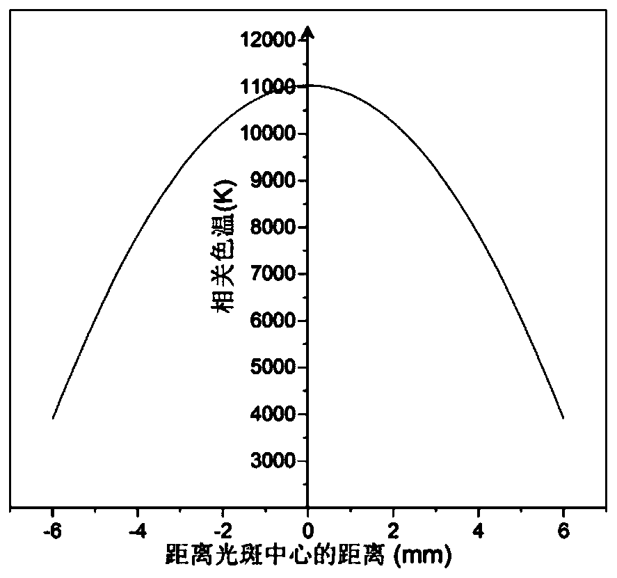
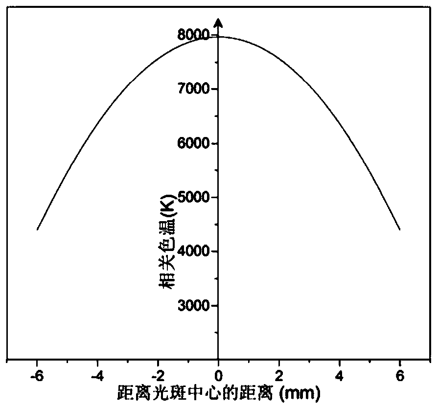
[0062] The device is irradiated with a blue laser with a power of 10 W and an emission wavelength of 450 nm, incident from the light-emitting layer. For the measurement results of spot uniformity, see Figure 4 . It can be seen that due to the existence of the structure (micropore) of hollow alumina microspheres, when the distance away from the center of the spot increases a lot, the correlated color temperature of...


PUM

PropertyMeasurementUnit
diameteraaaaaaaaaa
thicknessaaaaaaaaaa
diameteraaaaaaaaaa

Abstract

The invention discloses a laser lighting assembly using hollow alumina microspheres and a manufacturing method thereof, and relates to the field of lighting. The laser lighting assembly is formed by mixing hollow alumina microspheres, low-melting-point glass powder, fluorescent powder and volatile organic matters, wherein the hollow alumina microspheres serve as a light scattering medium, the inner diameter of the hollow alumina microspheres is 50-500 nm, the outer diameter of the hollow alumina microspheres is 400 nm to 1 micron, and the melting point range of the low-melting-point glass powder is 500-650 DEG C. The method comprises the following steps: uniformly mixing hollow alumina microspheres, low-melting-point glass powder, fluorescent powder and volatile organic matters to prepareslurry; coating the surfaces of sapphires with the slurry, sintering at high temperature, cooling, and removing a sintered flaky substance containing the hollow alumina microspheres, the fluorescent powder and the low-melting-point glass from the surfaces of the sapphires for supporting, namely obtaining the laser lighting assembly using the hollow alumina microspheres.

Description

technical field [0001] The invention relates to the lighting field, in particular to a laser lighting assembly using hollow alumina microspheres and a manufacturing method thereof. Background technique [0002] In the field of lighting, we will continue to move forward with the progress of society as a whole. From the initial reliance on animal and vegetable oils and fossil fuels, to incandescent lamps and gas discharge lamps (fluorescent lamps), then in the 1990s, relatively energy-saving and efficient LED white light lighting became popular. Recently, as the cost of laser diodes has gradually decreased and their performance has stabilized, it has gradually become possible to use lasers as illumination sources. [0003] Laser lighting is divided into visible light laser lighting and infrared laser lighting. [0004] Visible light laser lighting is divided into the following two types according to the principle: blue light excites fluorescent substances to realize white li...

Claims


Application Information

Patent Timeline
Patent Type & Authority Applications(China)
IPC IPC(8): F21K9/90F21Y115/10
Inventor 解荣军郑鹏周天亮
Owner XIAMEN UNIV
Why Eureka
Eureka Blog
Learn More