Low profile array antenna based on Luneburg lens array

A Lumberg lens and array antenna technology, which is applied to antenna combinations, antennas, antenna arrays and other directions with different interactions, can solve the problems of large volume and power consumption, high cost, limited trial scenarios, etc., and achieve market adaptability Strong, easy to control cost, reduce complexity and design difficulty

Active Publication Date: 2019-06-04
HEFEI RHOSOON INTELLIGENT TECH CO LTD
View PDF6 Cites 10 Cited by
  • Summary
  • Abstract
  • Description
  • Claims
  • Application Information

AI Technical Summary

Problems solved by technology

The scheme of multiple antenna units under a Lumber sphere, such as the general phased array scheme, that is, one antenna unit connected to one TR component, requires high cost, large volume and large power consumption, which limits the trial scenario

Method used


Image

  • Low profile array antenna based on Luneburg lens array
  • Low profile array antenna based on Luneburg lens array
  • Low profile array antenna based on Luneburg lens array

Examples


Embodiment 1

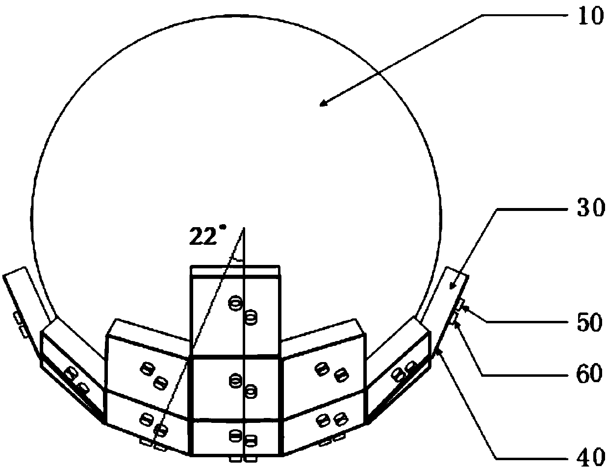
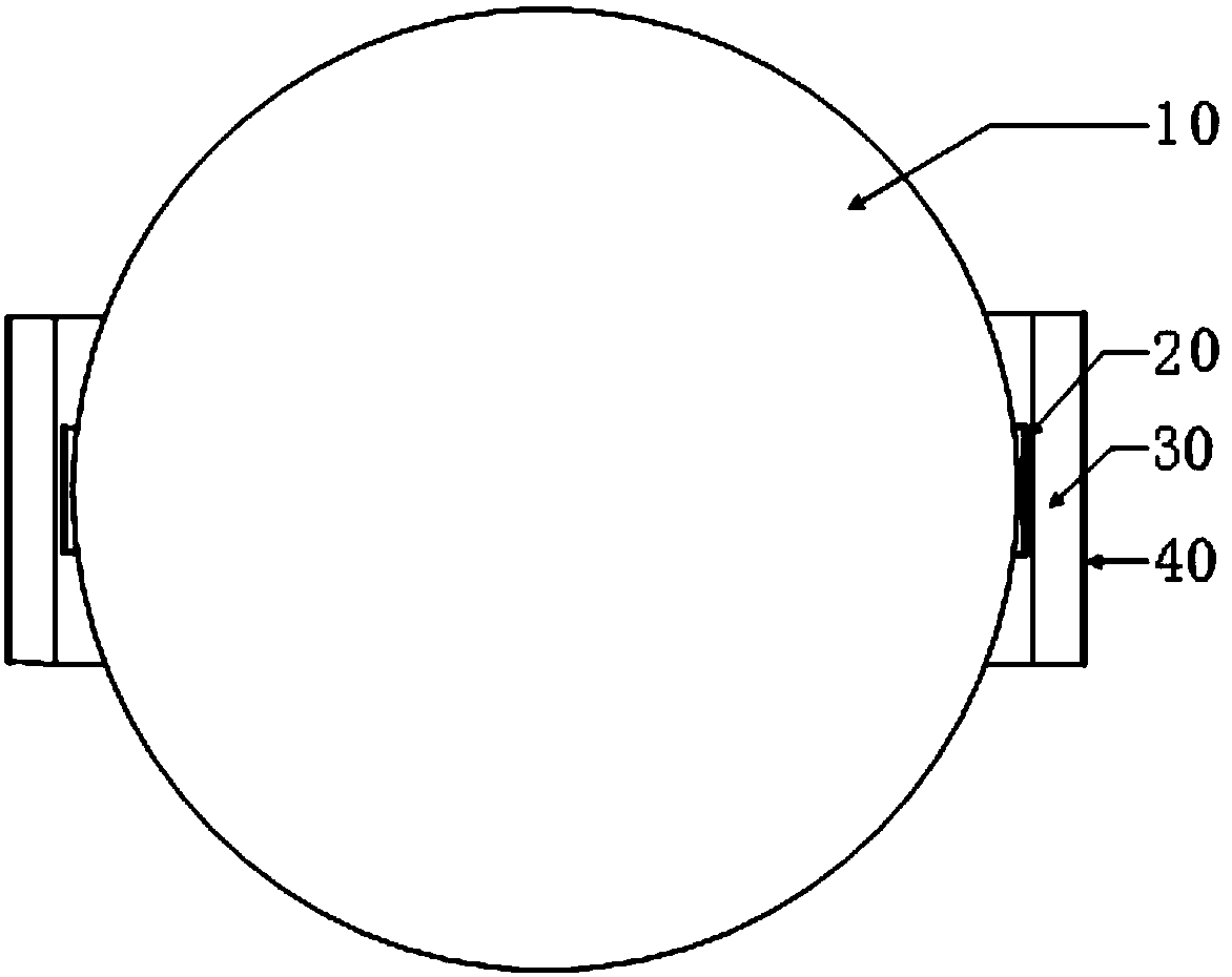
[0058] Lunberg lens unit 10, such as figure 1 , figure 2 , image 3 As shown, it is a sphere with a diameter of 140 mm, which is composed of upper and lower symmetrical upper and lower hemispheres. Each hemisphere is divided into multiple layers. The more layers, the better the performance. However, considering the difficulty of processing, this example gives 12 layers. Each layer is composed of three-dimensional cross unit structure. The center of each cross unit is a cube, and from the outer edge of the sphere to the center, the volume of the cube becomes larger and larger, so that the Lunberg lens unit 10 is a dielectric sphere antenna with a gradient permittivity structure, which can transmit light from all directions. The microwave signal converges to a point on the surface of the lens, which can realize the convergence and directional emission of electromagnetic waves. Its dielectric constant distribution satisfies the dielectric constant distribution of a spherical ...

Embodiment 2

[0083] Compared with Embodiment 1, this embodiment has the following differences:

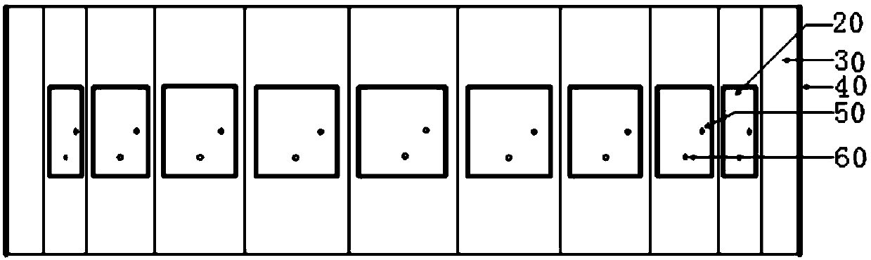
[0084] For the antenna unit, the upper surface metal layer 20 and the lower surface metal layer 40 are metal conductor copper with a thickness of 0.018 mm. The metal layer on the lower surface constitutes the ground of the antenna, and the size is 28mm×28mm. The dielectric substrate 30 is a rectangular RogersRT / duroid6010 dielectric board with a dielectric constant of 10.2, a thickness of 8 mm, and a size of 28 mm×28 mm.

[0085] Curved antenna arrays, such as Figure 11 As shown, the microstrip antenna array placed on the surface of each Lunberg lens unit 10 is formed by 25 microstrip antenna units arranged along the arc surface, specifically: 7 of the 25 antenna units are arranged side by side in an arc , 5 antenna units, 3 antenna units, and 1 antenna unit are sequentially arranged outward on both sides thereof, finally forming an arc-shaped (bowl-shaped) structure.

[0086] Lumberg lense...

Embodiment 3

[0095] Such as Figure 18 As shown, a low-profile array antenna based on a Luneburg lens array includes 16 Luneburg lenses and transceiver components; the 16 Luneburg lenses are arranged on the same horizontal plane; the Luneburg lens includes a Luneburg lens unit and is fixed on a Luneberg Antenna array on the surface of the lens element; the antenna array consists of 16 antenna elements.

[0096] The transceiver component includes a receiving module and a transmitting module:

[0097] The receiving module includes 16 first signal processing units, a synthesizer, a first attenuation controller, and a first phase shift controller; each first signal processing unit includes 16 first filters, 16 first low-noise amplifiers, 1 first multiplexer, several first adjustable attenuators, and several first phase shifters; the number of the first adjustable attenuators is the same as that of the first phase shifters, and the first multiplexer One or more signals that meet the requireme...


PUM


Abstract

The invention provides a low profile array antenna based on a Luneburg lens array. The low profile array antenna comprises m Luneburg lenses and a transceiving assembly, wherein the m Luneburg lensesare arranged on the same horizontal plane; each Luneburg lens comprises a Luneburg lens unit and an antenna array fixed to the surface of the Luneburg lens unit, and antenna units with identical pointing angles on different Luneburg lens units are antenna units at the same position; the transceiving assembly comprises a receiving module and a transmitting module; the n antenna units receive n paths of signals; the receiving module selects a plurality of paths of signals from the n paths of signals, and combines the plurality of paths of signals into a path of signals and outputs the path of signals to the transmitting module; and the transmitting module processes the path of signals and realizes multi-path signal output. The low profile array antenna has the advantages of realizing large-angle beam scanning through arranging the antenna arrays on the surface of the single Luneburg lens unit and sequentially feeding the antenna units at the same position in the antenna array on the surface of each Luneburg lens unit, and reducing the complexity and design difficulty of an antenna feeding network.

Description

technical field [0001] The invention relates to the technical field of antennas, in particular to a low-profile array antenna based on Lunberg lens arrays. Background technique [0002] The beam scanning range of an array antenna is an important performance index. In 2005, "Antenna Theory: Analysis and Design" (Constantine A. Balanis, Antenna Theory: Analysis and Design, edited by Constantine A. Balanis and published by John Wiley & Sons, Inc., Hoboken, New Jersey, USA, John Wiley&Sons, Inc., Hoboken, New Jersey: 2005, Page(s): 283-384) introduced the characteristics and design methods of traditional planar phased arrays. When the traditional planar phased array antenna scans to a large angle, the gain of the array radiation pattern will decrease and the sidelobe will increase due to the reduction of the equivalent aperture of the antenna array. The scanning angle usually does not exceed ±40°, which is limited. The scanning angle limits its application. [0003] In 1964, ...

Claims


Application Information

Patent Timeline
Patent Type & Authority Applications(China)
IPC IPC(8): H01Q1/50H01Q3/24H01Q15/02H01Q21/00H01Q21/06H01Q21/20H01Q21/29
Inventor 桂万如邓庆勇杨如意季文涛刘培帅黄金梅王立
Owner HEFEI RHOSOON INTELLIGENT TECH CO LTD
Why Eureka
Try Eureka